GORE® Universal Pipe Gasket (Style 800) for Reliable Industrial Sealing
Reliably seal a broad range of flange materials with this low stress-to-seal, dimensionally stable and chemically resistant 100% expanded PTFE pipe gasket.
A Universal Pipe Gasket Seal for Multiple Flange Materials
GORE® Universal Pipe Gasket (Style 800) provides a reliable seal for steel, glass-lined steel (GLS) and fiber-reinforced plastic flanges (FRP.) These highly conformable 100% ePTFE pipe gaskets withstand the full spectrum of strong acid, alkali, and solvent process media, as well as thermal cycling and elevated temperatures, and reliably seal irregular surfaces.
The patented construction of GORE Universal Pipe Gasket (Style 800) creates a tight initial seal and maintains a reliable long-term seal.
Proprietary, Patented Technology
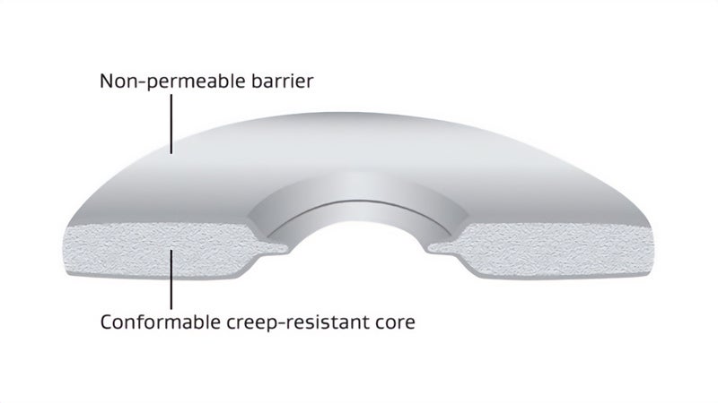
GORE Universal Pipe Gasket (Style 800) uniquely combines two patented construction elements, each made of 100% expanded PTFE (ePTFE).
- A non-permeable barrier layer covers the inside diameter and gasket flange faces. This creates a tight seal at low gasket stress and protects the flange surfaces.
- A conformable-yet-strong interior provides superior resistance to creep and cold flow.
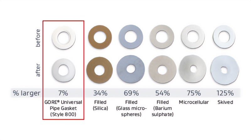
GORE Universal Pipe Gasket’s superior creep resistance outperforms other non-metallic flat gaskets made of ordinary PTFE. (Tested at 34.5 MPa (5000 psi) load, 230 °C (446 °F) for 15 minutes.)
Long-Term Reliable Sealing
With superior resistance to creep and cold flow, GORE Universal Pipe Gasket (Style 800) retains its dimensional stability through thermal and pressure cycles. This avoids gasket intrusion into the bore, and maintains bolt load, enabling a long-term reliable pipe seal. Plus, GORE Universal Pipe Gasket (Style 800) is highly conformable to common flange imperfections, creating a tight seal in challenging conditions.
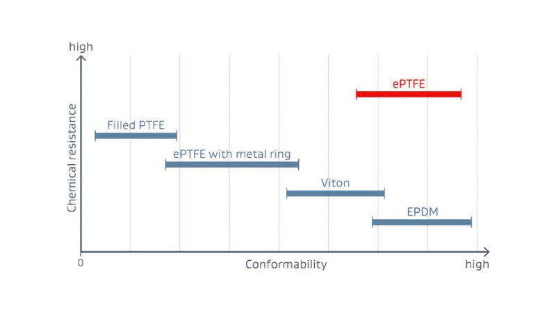
Gore’s combination of exceptional chemical resistance and exceptional conformability outperforms other gasketing materials.
Chemical Resistance + Conformability Outperforms Other Gasketing
Only GORE Universal Pipe Gasket (Style 800) offers this unique combination of chemical resistance and conformability. That’s why its performance as a pipe flange seal is unmatched by other gasketing materials.
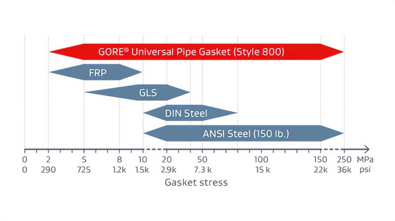
GORE Universal Pipe Gasket (Style 800) reliably seals across the full range of flange stresses.
One Gasket, Many Applications
Using GORE Universal Pipe Gasket (Style 800) across multiple pipe flange materials and process media can:
- Streamline gasket ordering and inventories.
- Standardize gasket selection and installation processes.
- Reduce the risk of choosing the “wrong” pipe gasket material, which could create process safety and downtime issues.
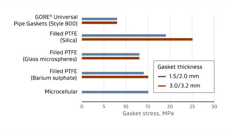
Compared to other gasketing materials, GORE Universal Pipe Gasket (Style 800) is more gas-tight, providing greater leak resistance at higher temperatures.
SOURCE: www.gasketdata.org
More Gas-Tight, for Reduced Emissions
In processes with elevated temperatures, GORE Universal Pipe Gasket (Style 800) is significantly more gas-tight than other non-metallic pipe flange seals.
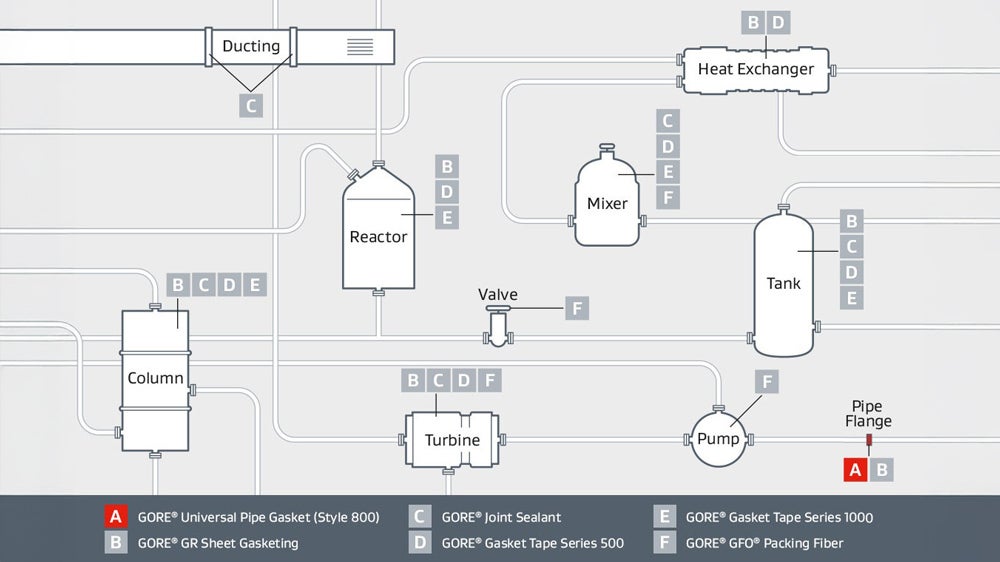
GORE Universal Pipe Gasket (Style 800) performs durably across a range of challenging applications, reliably sealing steel, glass-lined steel (GLS) and fiber-reinforced plastic (FRP) flanges.
GORE Universal Pipe Gasket (Style 800) offers a unified material solution for sealing a wide range of flange materials in a wide range of processes and industries.
Processes involving highly-aggressive media or thermal cycling, as in:
- Chemical processing
- Pulp and paper manufacturing
- Mining and minerals
- Semiconductor manufacturing
- Power generation
- Food processing
Requirements that challenge other non-metallic flat gaskets, such as:
- Exhaust-flange sealant
- High-pressure flange sealant
- High-temperature flange sealant
- Flange gasket for sulfuric acid and many other highly aggressive media
Equipment flanges of steel, glass-lined steel (GLS), and fiber-reinforced plastic (FRP) used in:
- Pipes
- Manways
Extensive Portfolio Available: Get Exact Style, Size and ID Option for Your Application
Gore offers a broad range of ring and full-face gaskets dimensioned for the major industry standards; ASME, EN and JIS.
Within these pipe gasket sizes, we also offer a section of ID options:
- Standard ID
- GLS ID: optimized for GLS flanges
- NPS ID: Nominal Pipe Size (Old Standard) for ductile iron and other specialty applications
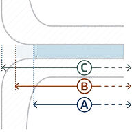
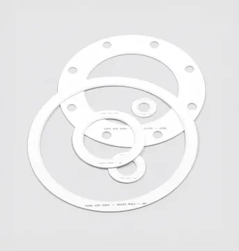
Inner diameter options for GORE® Universal Pipe Gasket (Style 800)
A. Standard ID:
for ASME B16.21 and EN 1514-1
- For general use in steel flanges
- ID per applicable standard
B. GLS ID Option:
for ASME B16.21 and EN 1514-1
- Best option for glass-lined steel flanges
- ID reduced to protect glass lining
C. NPS ID Option:
for ASME B16.21
- Required for ductile iron pipe and other specialty applications
- ID = Nominal Pipe Size in inches ("old standard")
GORE Universal Pipe Gasket (Style 800) is versatile enough to seal a wide range of flange materials, and our extensive portfolio makes it easy to get the exact style, size and ID option that’s right for your application. Refer to information below in Technical Specs for all the sizes and standards available.
It’s easy to choose the right gasket for each flange gasket size: Key information is clearly printed on every genuine GORE Universal Pipe Gasket (Style 800).
Technical Information
| Material | 100% expanded PTFE (polytetrafluoroethylene), with multidirectional strength |
|---|---|
| Chemical Resistance | Chemical resistance to all media pH 0-14, except molten alkali metals and elemental fluorine. |
| Operating Range | The maximum applicable pressure and temperature depend mainly on the equipment and installation.
For applications outside the typical use range, Gore recommends an application specific engineering design calculation and extra care during installation. Also, consider retorquing after a thermal cycle when the equipment has returned to an ambient temperature condition. Please contact Gore if further guidance is required. |
| Shelf Life | Expanded PTFE is not subject to aging and can be stored indefinitely. |
(1) absolute pressure of 1 mmHg (Torr) = 133 Pa = 1.33 mbar = 0.019 psi
GORE Universal Pipe Gasket (Style 800) is available in ring or full-face styles, manufactured to ASME, EN or JIS standards.
For other sizes or custom gaskets, contact Gore.
Standard Product Offering
| Gasket Standard | Gasket Type | Pressure Class | Product | ||
|---|---|---|---|---|---|
| 1.5 mm (1/16") | 3.0 mm (1/8") | 6.0 mm (1/4") | |||
| ASME B16.21 | Ring | CL 150 | NPS 1/2 to 24 | NPS 1/2 to 24 | N/A |
| CL 300 | |||||
| Full Face | CL 150 | NPS 1/2 to 24 | |||
| CL 300 | |||||
| ASME B16.21 GLS ID(2) | Ring | CL 150 | N/A | N/A | NPS 1/2 to 24 |
| CL 300 | |||||
| ASME B16.21 NPS ID(3) | Ring | CL 150 | NPS 1/2 to 12 | NPS 1/2 to 12 | NPS 1/2 to 12 |
| CL 300 | |||||
| Full Face | CL 150 | ||||
| CL 300 | |||||
| EN 1514-1 | Ring (IBC) | PN 2.5 | DN 10 to 600 | DN 10 to 600 | N/A |
| PN 6 | |||||
| PN 10 | DN 10 to 600 | DN 10 to 800 | N/A | ||
| PN 16 | DN 10 to 600 | DN 10 to 600 | N/A | ||
| PN 25 | |||||
| PN 40 | |||||
| EN 1514-1 GLS ID(2) | Ring (IBC) | PN 10 | N/A | N/A | DN 15 to 600 |
(2) Reduced inner diameter optimized for glass lined steel applications.
(3) Reduced inner diameter for ductile iron pipe and other specialty applications.
Test Data
Test Results
| Thickness | Compressibility (average of 3 tests) | Recovery (average of 3 tests) | |
|---|---|---|---|
ASTM F36-95 Procedure L
| 1.14 mm (0.045") | 55% | 16% |
Test Method
The ASTM F36 test method covers determination of the short-time compressibility and recovery at room temperature of sheet-gasket materials. It is not intended as a test for compressibility under prolonged stress application, generally referred to as "creep."
Source: ASTM International. Standard Test Method for Compressibility and Recovery of Gasket Materials - Designation: F36–99 (Reapproved 2009)
Test Results
| Thickness | Relaxation (average of 3 tests) | |
|---|---|---|
ASTM F38-95 Method B
| 0.8 mm (0.030") | 11% |
Test Method
ASTM F38 provides a means of measuring the amount of creep relaxation of a gasket material at a predetermined time after a compressive stress has been applied. This test method is designed to compare related materials under controlled conditions and their ability to maintain a given compressive stress as a function of time.
Source: ASTM International. Standard Test Methods for Creep Relaxation of a Gasket Material - Designation: ASTM F38-00 (2014)
Test Results
| Thickness | Leak rate | |
|---|---|---|
ASTM F37-95 Test Method B
| 0.8 mm (0.031") | 0.48 ml/h |
Test Method
ASTM F37 provides a means of evaluating the sealing properties of sheet and solid form-in-place gasket materials at room temperature. This test method is designed to compare gasket materials under controlled conditions and to provide a precise measure of leakage rate.
Source: ASTM International. Standard Test Methods for Sealability of Gasket Materials - Designation: ASTM F37-06 (2013)
Test Results
| Gasket Thickness | % Relaxation (Average of 3 Tests) | Helium Leak Rate before aging (mg/s) | Helium Leak Rate after aging (mg/s) | |
|---|---|---|---|---|
| ARLA1 | 1.5 mm 1/16" | 23 | 2.86E-05 | <1E-07 |
| 3.0 mm 1/8" | 51 | 1.29E-04 | <1E-07 |
1 Compressive stress 34.5 MPa (5000 psi); 4 days at 315 °C (600 °F); 55 bar (800 psig) Helium
Test Method
This test method is currently being proposed as a new ASTM test method by the Committee F03 on Gaskets. ARLA determines the long term (aged) relaxation, leakage, weight loss and adhesion performance of gasket materials for pressurized bolted flanged connections. A mechanical integrity check of the material is also done. The method applies mainly to circular gasket products typically used in process or power plant pressure vessels and piping.
Source: ASTM International. New Test Method for AGED RELAXATION LEAKAGE ADHESION PERFORMANCE of Gaskets - Designation: ASTM WK26065
General Test Procedure
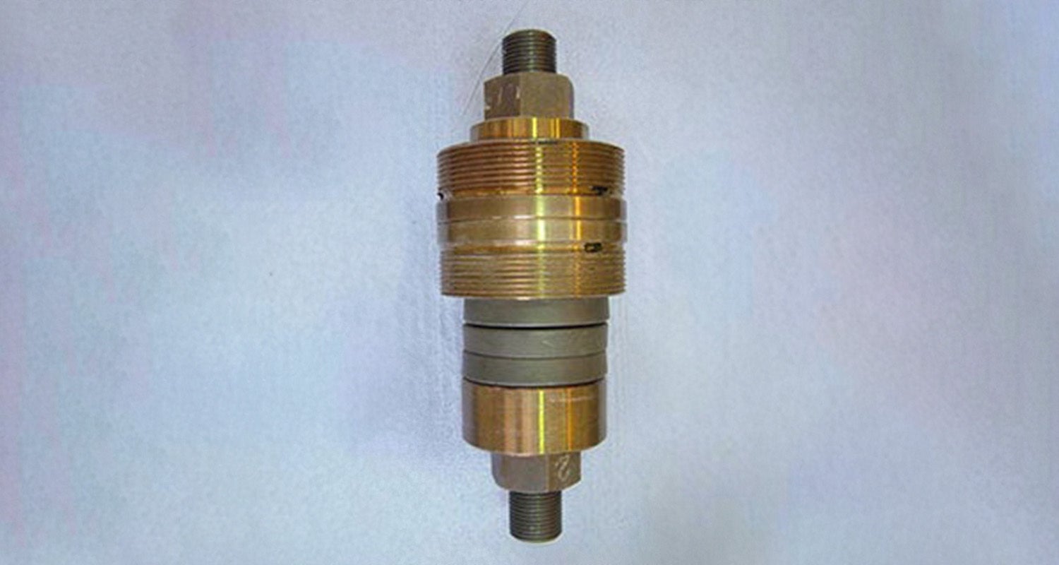
ARLA Test Fixture
- Place the gasket in the ARLA fixture
- Measure the distance between platens
- Load the gasket to initial compressive stress
- Measure the stud length
- Measure the distance between platens
- Measure the leak rate (using a Helium Mass Spectrometer) using helium gas at 800 psig
- Age by placing the loaded fixture in a non-circulating air oven
- Remove the fixture from the oven and cool to room temperature
- Measure the stud length
- Measure the distance between platens
Test Results
| Thickness | Exposure Temperature | Initial Gasket Stress | Test Step 1 | Test Step 2 | |
|---|---|---|---|---|---|
| VDI 2200 (06-2007) DN40 / PN40 Steel | 3.0 mm (1/8") | 230 °C (446 °F) | 30 MPa (4350 psi) | Yes, 60 bar (870 psi) | Yes, 60 bar (870 psi) |
Test Method
"The aim of the VDI guideline is to analyze and organize the applicable seal connection conditions based on the technical standard. Furthermore, to complete the conditions, including latest research results, and advise the user in selection, interpretation, design, and assembling of flange joints in particular consideration of the gaskets."(1) "The here described blowout safety test of seals in sealing systems with even flanges corresponds with the current state of test engineering [...] a seal itself cannot accomplish blowout safety. It always depends on the entire system of the flange joint."
General Test Procedure
- Installation of seal with installation surface pressure in four steps (25 %, 50 %, 75 % and 100 % of bolt force through crosswise tightening). Installation surface pressure and seal thickness are to be indicated in the test record. The lift-off force, caused by the nominal pressure, referring to the middle seal diameter, shall additionally be considered in all testing steps.
- Retightening to installation surface pressure after 5 minutes.
- Flange heating to temperature with 2 K/min in recirculation furnace or using inside heated cartridges.
- Maintenance of thermal storage temperature for minimum 48 hours.
- Cooling down of the flange to ambient temperature.
- Measurement of the remaining surface pressure.
Test Step 1
The blowout safety test is performed with nitrogen up to the 1.5-fold of the nominal pressure. Tests with higher pressures are allowed, if required. The internal pressure is to be increased stepwise, in steps of 5 bar to the above mentioned pressure. The holding period per pressure stage amounts to a minimum of 2 min.
As "blowout" is defined, if, within 5 s, a pressure decay of Δp ≥ 1 bar· (V0 = test room volume) is exceeded. The achieved internal pressure is to be indicated in the test record. If blowout did not occur until the maximum test pressure, the test is to be continued according to test step 2.
Test Step 2
The internal pressure is discharged and the surface pressure is reduced to 5 N/mm2 with regard to lifting force caused by the internal pressure. Variations of the surface pressure are to be stated in the testing report."(2)
(1) Source: Verein Deutscher Ingenieure e. V.: VDI 2200: Tight flange connections - Selection, calculation, design and assembly of bolted flange connections, June 2007, page 4
(2) Source: ibidem, page 64
Test Results
| Gasket Thickness | Blowout Temperature | Blowout Stress | Blowout Pressure | Trial Gasket Temperature Tgr | |
|---|---|---|---|---|---|
| HOBT with Cycling Draft 71 | 3.0 mm (1/8") | 385 °C (725 °F) | 7.0 MPa (1008 psi) | 30 bar (435 psig) | Actual: Greater than 384 °C (723 °F) Limited to: 315 °C (600 °F) |
1 NPS 3 Class 150 Slip-on Flange at 34.5 +/- 1.7 MPa (5000 +/- 250 psi), 30 bar (435 psig) Helium
Test Method
This test method is currently being proposed as a new ASTM test method by the Committee F03 on Gaskets. This test method provides a means to determine realistic temperature limits for polytetrafluoroethylene (PTFE) based sheet or sheet-like gaskets to assist in avoiding catastrophic failure or blowout. This test method focuses on flanged joints common in the chemical process industry for moderate temperature ASME B16.5 Class 150 and Class 300 services.
Source: ASTM International. New Test Method for Hot Blowout and Thermal Cycling Performance for Polytetrafluoroethylene (PTFE) Sheet or Sheet-Like Gaskets - Designation: ASTM WK26064
General Test Procedure (Draft 7)
- A gasket is loaded in a Hot Blow Out Test Rig, which is comprised of NPS 3 Class 150 or Class 300 raised face flanges. Using a torque wrench and best installation practices, the specified compressive stress is applied to the gasket.
- A waiting period for gasket creep and relaxation of 30 minutes is observed before the gasket is reloaded to the specified gasket stress.
- Another 30 minutes waiting period is observed before the rig is pressurized with helium gas.
- For HOBT without thermal cycles, once the pressure is applied, the temperature is increased up to 648.9 °C (1200 °F) maximum at a 16.1 °C (3 °F) per minute rate until blow-out or maximum temperature of the rig is reached.
- For HOBT with thermal cycles, once the pressure is applied, the temperature is increased at 16.1 °C (3 °F) per minute rate. The fixture is then cooled to room temperature. This cycle is repeated two more times for a total of three thermal cycles per test.
The procedure consists of three tests:
Test 1: HOBT without thermal cycles.
Test 2: HOBT with 3 thermal cycles using temperature estimation from Test 1.
Test 3: HOBT with 3 thermal cycles using temperature estimation from Test 2.
Test Results
| ROTT Draft 9 | GORE Universal Pipe Gasket (Style 800) | |
|---|---|---|
| Soft Gasket Test | Gasket Thickness: 1/16" | Gasket Thickness: 1/8" |
| Gb (psi) | 441 | 155 |
| a | 0.3 | 0.411 |
| Gs (psi) | 8.55E-01 | 5.41E-02 |
| Tpmin | 2041 | 3210 |
| S100 (psi) | 45893 | 39160 |
| S1000 (psi) | 3495 | 2652 |
| S10000 (psi) | 6968 | 6839 |
| Maximum Allowable Gasket Stress (psi) | Greater than 40030 (Equipment Max) | 36260 |
Test Method
This test method is currently being proposed as a new recommended practice for Gasket Constants for Bolted Joint Design by the Committee F03 on Gaskets. This practice determines room temperature gasket tightness design constants for pressurized bolted flanged connections such as those designed in accordance with The ASME Boiler & Pressure Vessel Code. It applies mainly to all types of circular gasket products and facings typically used in process or power plant pressure vessels, heat exchangers and piping including solid metal, jacketed, spiral wound and sheet type gaskets. As an option, the maximum assembly stress for those gaskets is also determined by this procedure.
Source: ASTM International. New Recommended Practice for GASKET CONSTANTS FOR BOLTED JOINT DESIGN - Designation: ASTM WK10193
Definitions of Test Parameters
| Gb | The gasket stress at Tp = 1 when loading the gasket. It indicates the initial gasket stress required to seat the gasket with tightness. |
|---|---|
| "a" | The slope obtained by linear regression. It indicates the capacity of the gasket to ensure tightness. |
| Gs | The gasket stress at Tp = 1 when unloading the gasket. It indicates the capacity of the gasket to maintain tightness when pressure is applied, as well as the gasket's sensitivity to unloading. |
| Tp | The Tightness Parameter is dimensionless. A value of 1 corresponds to a Helium leak rate of 1 mg/s under atmospheric pressure for a gasket with an outside diameter of 150 mm. Note: the greater the Tp, the greater the gasket tightness. |
| Tpmax | The maximum tightness obtained when loading the gasket. |
| Tpmin | The minimum tightness obtained when unloading the gasket. |
General Test Procedure for Soft Gaskets (Draft 9)
- A gasket is placed in a hydraulic flat platen test rig.
- A series of 3 loadings and unloading cycles is applied during which leak rate is measured at each stress level. Depending on the step, the system is pressurized to either 27.5 bar (399 psi) or 55 bar (798 psi) using helium gas. The holding time at each step is dependent on when a leak rate stabilizes, with a minimum hold time of 1 minute and a maximum hold time of 5 hours.
- The data collected is grouped into two Parts, Part A and Part B, and analyzed to generate the test parameters. Part A represents the initial seating performance of a gasket during initial flange tightening. Data from Part A is used to determine Gb, "a", and Tpmax. Part B simulates actual operating conditions. Data from Part B is used to determine Gs and Tpmin.
General Test Procedure for Crush (Draft 9)
- The gasket stress is restored to S1 level.
- Loading cycles, with gradually increasing compression stresses, are applied on the gasket during which leak rate is measured at each stress level. The system is pressurized to 27.5 bar (399 psi) using helium gas. The holding time shall not exceed 15 minutes at each stress level.
- The test is complete when the leak rate at a stress level exceeds the leak rate observed at S1 level or when the maximum load of the equipment is reached.
- Maximum Allowable Stress is the maximum stress level where S1 leak rates were maintained.
Gasket Design Factors
Test Results
Please find below the test results by tape thickness.
- GORE® Universal Pipe Gasket (Style 800) in 1.5 mm (1/16")
- GORE® Universal Pipe Gasket (Style 800) in 3 mm (1/8")
- GORE® Universal Pipe Gasket (Style 800) in 6 mm (1/4")
Note: If the gasket thickness is not directly listed above, use the data from the next higher thickness.
Test Method
EN 13555 provides the test method for generating the gasket parameters used in EN 1591-1 calculations.
Gasket Constant Definitions
| PQR | A measure of creep relaxation at a predefined temperature. It is the ratio between the gasket stress after relaxation and the initial gasket stress. The ideal PQR value is 1. The closer the test value is to the ideal value, the lower the loss of gasket stress. |
|---|---|
| Qmin(L) | The minimum required gasket stress at ambient temperature for a certain leakage class L when the seal is first installed. |
| QSmin(L) | The minimum required gasket stress for a certain leakage class L in service. |
| QSmax | The maximum gasket stress that may be applied on the gasket, without damage or intrusion into the bore, at the indicated temperatures. It depends on the temperature and the gasket thickness. |
| EG | The recovery (elastic behavior) of a seal at load reduction and is related to the modulus of elasticity. It depends on the applied gasket stress, the seal thickness and the temperature. |
General Test Method Description
| PQR | Creep Relaxation is measured at different temperatures, initial gasket stress, seal thickness values and flange stiffness values. The seal initially is exposed to the predefined gasket stress, then the temperature is increased and maintained for four hours. The residual gasket stress is then measured. |
|---|---|
| Qmin; QSmin | A load is applied to and removed from the seal in predefined increments, with the leakage being measured constantly. The internal pressure is usually 40 bar (test gas: helium). |
| QSmax; EG | The gasket stress is increased cyclically and then reduced to 1/3 of the previous gasket stress. The seal thickness is then measured. The test is repeated at various temperatures. The EG value is calculated from the load reductions and thickness changes. For QSmax, a sudden drop in seal thickness indicates failure. If a sudden drop occurs, the value of the loading step before failure is taken. In case no failure occurs, the maximum possible gasket stress of the test equipment is taken. The identified value is then used as the initial stress in a PQR test to verify the final QSmax under constant loading. |
Test Results
Because GORE® Universal Pipe Gasket (Style 800) can be used in a wide range of applications, Gore wanted to ensure m&y values were applicable to each application type. Therefore, Gore modified the archived m&y test protocol to account for the influence of internal pressure and desired sealability. The values below reflect a T3 seal as tested per CETIM, reference report no. 774630/6J1/a.
| Flange Type | Plastic/FRP | Glass-lined Steel | Steel |
|---|---|---|---|
| Maximum Internal Pressure (psi) | 290 | 580 | 580 |
| m | 2.5 | 1.4 | 2.4 |
| y (psi) | 290 | 725 | 1,500 |
Test Method
m & y are gasket constants used for flange design as specified in the ASME Boiler and Pressure Vessel Research Code Division 1 Section VIII Appendix 2. Leak Rates versus Y stresses and m factor for Gaskets is currently being proposed as a new test method in the ASTM F03 Working Group.
Gasket Constant Definitions
m, maintenance factor, is a factor that describes the amount of additional preload required to maintain the compressive load on a gasket after internal pressure is applied to a joint.
y, seating stress, is the minimum compressive stress (psi) required to achieve an initial seal.
Test Results
For GORE Universal Pipe Gasket (Style 800) in 3 mm thickness and with an internal pressure of 40 bar (580 psi), this results in:
| k1 | 1.25 · bD |
|---|---|
| k0KD | 5 MPa · bD |
| k0KDϑ | 80 MPa · bD temperature ϑ = 230°C (446°F) |
Test Method
There are no specific test standards for AD 2000 B 7 Gasket Parameters. However, an estimation is provided below. The 2015 edition of "AD 2000-Merkblatt B 7" refers to EN 13555 as a test standard(1) and uses table 9 from VDI 2200(2) for the conversion method. Please note that VDI 2200 states that such a conversion is invalid due to the different measurement methods. "Only the method according to DIN EN 1591-1 and AD 2000 in conjunction with DIN EN 1591-1 and FE analysis can be used for providing stability and leak tightness."(3)
Gore supports the use of the AD 2000-Merkblatt B 7 and provides the necessary gasket parameters below.
There are the following relations(1):
k0KD ≙ Qmin · bD
k1 ≙ (QSmin / p) · bD since m ≙ (QSmin / p)(4)
k0KDϑ ≙ QSmax · bD
| Qmin | minimum required gasket stress at ambient temperature when the seal is first installed (based on EN 13555) |
|---|---|
| QSmin | minimum required gasket stress in service (based on EN 13555) |
| QSmax | maximum gasket stress that may be applied on the gasket at an indicated temperature ϑ (based on EN 13555) |
| bD | width of the gasket |
| p | internal pressure of the media |
| k1 | AD 2000 B 7 gasket parameter for service condition |
| k0KD | AD 2000 B 7 gasket parameter for gasket deformation |
| k0KDϑ | AD 2000 B 7 gasket parameter for gasket deformation in service at temperature ϑ |
If necessary for a specific application, Gore recommends to do individual conversions based on data from EN 13555.
The use of the general values given in table 1 of AD 2000-Merkblatt B 7(5) is not broadly recommended. However they may be applicable depending on the given situation.
Please also note that the quoted standards of DIN 2690 to DIN 2692 were superseded by EN 1514-1 in 1997.
(1) Arbeitsgemeinschaft Druckbehälter: AD 2000-Merkblatt B 7, Berechnung von Druckbehältern, Schrauben, Seite 4, 7.1.2.4, April 2015.
(2) Verein Deutscher Ingenieure e. V.: VDI 2200, Tight flange connections - Selection, calculation, design and assembly of bolted flange connections, page 36, table 9, June 2007.
(3) Verein Deutscher Ingenieure e. V.: VDI 2290, Emission Control - Sealing constants for flange connections, page 8, June 2012.
(4) Please note that factor m = QSmin / p was defined by DIN V 2505 which was superseded by EN 1591-1 where m is no longer used.
(5) Arbeitsgemeinschaft Druckbehälter: AD 2000-Merkblatt B 7, Berechnung von Druckbehältern, Schrauben, Seite 6, Tabelle 1, April 2015.
Certificates & Application Information
| Type | Description | File |
|---|---|---|
| Oxygen Service (BAM) | The Federal Institute for Materials Research and Testing (BAM) tests the sealing material compatibility for use in flanged connections with liquid and gaseous oxygen. Further information on the test procedure and the result can be found in the following test report. | Download |
| Chlorine Service | Eurochlor's publication on Experience of Gaskets in Liquid Chlorine and Dry or Wet Chlorine Gas Service and the Chlorine Institute's Pamphlet 95 Gaskets for Chlorine Service cover gaskets for both dry and wet chlorine service and highlight materials that have found user acceptance through field-testing and member company experience. GORE® GR Sheet Gasketing and GORE Universal Pipe Gasket (Style 800) are both listed in these publications. The documents are available from the respective organizations. | |
| Marine and Offshore Applications | GORE® Universal Pipe Gasket (Style 800) has received a PDA (Product Design Assessment) certificate under the ABS Approval Program. | Download |
| Leachable Fluoride and Chloride | This test analyzes leachable water-soluble fluoride and chloride ions which can induce flange corrosion. The samples are leached for 24 hours at approximately 95 °C in demineralized water. Contact Gore for further information if this testing is required for your application. | |
| Safety Information | GORE® Gasketing products meet the definition of an article; therefore, a Material Safety Data Sheet (MSDS) or Safety Data Sheet (SDS) is not required. However, for your convenience, a Product Safety Sheet, which details the intended use and proper handling of our articles, is provided. | Download |
| Gore Quality Management System | The Gore Sealant Technologies Quality Management System is certified in accordance with ISO 9001. | |
| Food Contact | Unprinted GORE® Universal Pipe Gasket (Style 800) meets the requirements for repeat-use food contact applications with all food types per FDA regulations 21CFR174.5 (d) (1-5), 21CFR177.1550 (and 21 CFR175.300 for products with red and green printing ink) and conform to the requirements of regulation (EC) No 1935/2004 including (EU) No 10/2011. Declaration of Compliance is available upon request. |
Featured Content
Explore More
Unprinted GORE® Universal Pipe Gasket (Style 800) conforms to the US FDA 21CFR and EU directive EC 1935/2004 requirements relating to food contact. Declaration of Compliance is available upon request.
Prefer to Call?
Have questions or unique requirements?
Our experts are here to guide you.