GORE® Joint Sealant for Large Steel Flanges
Versatile and easy-to-install, this 100% ePTFE sealing cord is a cost-effective solution for large steel flanges in general-use applications.
Reliable and Versatile Sealing for Steel Flanges
GORE® Joint Sealant, the first ePTFE form-in-place gasket material, seals steel flanges with large diameters, rectangular or irregular shapes, and rough or pitted surfaces, forming a thin yet strong seal when compressed. Chemical-resistant GORE Joint Sealant can withstand challenging process conditions and aggressive media, sealing applications where available bolt loads are low or in applications that demand a gas-tight sealant.
Gore’s Expanded Polytetrafluoroethylene Technology
GORE Joint Sealant is made of 100% monoaxially expanded PTFE (ePTFE), using Gore’s expansion technology to create a high degree of fibrillation.
High fibrillation is what improves the joint sealant material’s strength and seal performance, and creates the soft, conformable surface that readily fills minor flange irregularities.
GORE Joint Sealant is versatile enough for use in strong alkali-, acid- and solvent-based chemical process systems, as it is chemically resistant to all media (pH 0-14) except molten/dissolved alkali metals and elemental fluorine.
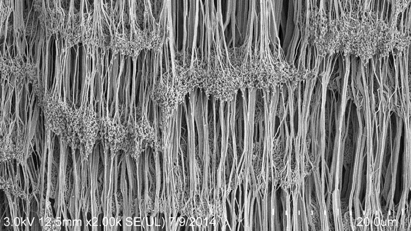
Gore’s expansion technology creates fibrils that enable GORE Joint Sealant to seal irregular flange surfaces more reliably.
Easy and Cost-Effective
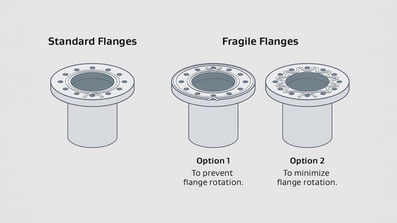
This rope gasket material can instantly be formed in place to fit any shape, regardless of flange size or complexity, or flange condition, forming a a tight durable seal that minimizes maintenance. It offers fast and easy installation options for fragile flanges, and for applications where flange rotation must be minimized or prevented. It is ideally suited to many Maintenance, Repair and Operations (MRO) teams because it seals reliably and is easy and cost-effective to install.
Save Time and Money
With GORE Joint Sealant, creating custom large gaskets on the spot is swift and simple, because your form in place gasket is immediately available.
- No need to wait for one to be fabricated off-site.
- No need for extra gaskets-and-seals procurement efforts to receive pallets, or requisition trucks or crane-lifts.
- No need for special handling or maintenance required.
- Even sealing vertical flanges is a one-person job.
GORE Joint Sealant instantly creates a tight seal on large, complex or fragile flanges.
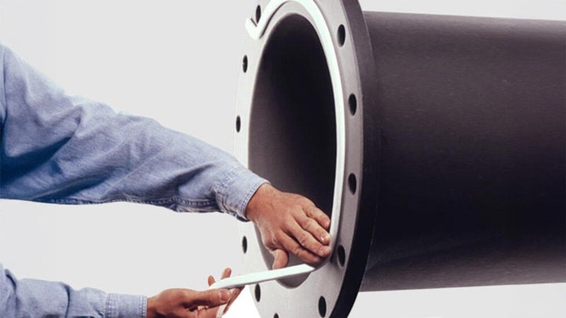
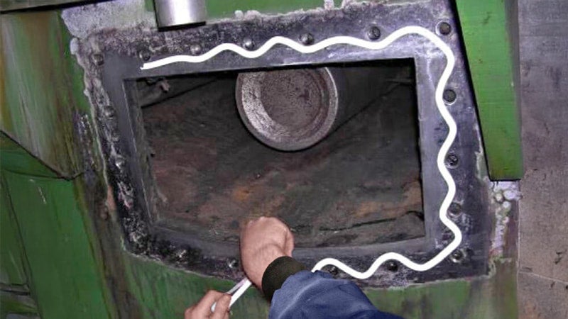
GORE Joint Sealant is simple for one person to install on both horizontal and vertical flanges.
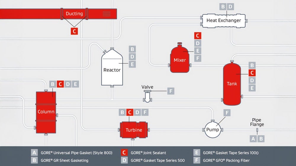
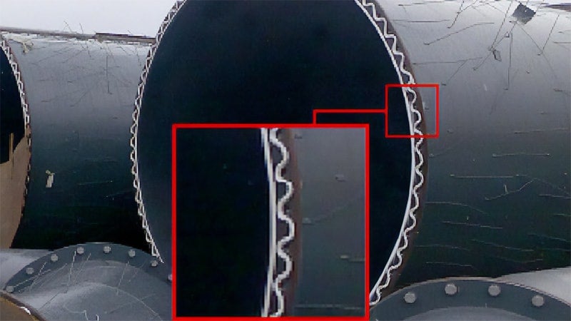
GORE® Gaskets by Application
GORE® Joint Sealant creates form in place gaskets that reliably seal steel flanges in ducting, columns, turbines, mixers and tanks.
Processes Using Highly Aggressive Media
- Chemical processing
- Pulp and paper
- Mining and minerals
- Semiconductor manufacturing
- Power generation
Processes Requiring an Expanded PTFE Joint Sealant Material
- Those that demand a high-temperature joint sealant
- Those that employ highly-corrosive media
- Those that need a gas-tight sealant or vacuum gasket cord
Large and/or Non-Standard Steel Equipment Flanges
- Tank manways
- Handholes and manholes
- Ductwork
- Housing covers
Technical Information
| Material |
|
|---|---|
| Temperature Range | -269 °C to +315 °C (-452 °F to +600 °F) |
| Chemical Resistance | Chemical resistance to all media pH 0-14, except molten alkali metals and elemental fluorine. |
| Operating Range | The maximum applicable pressure and temperature depend mainly on the equipment and installation.
|
| Shelf Life | Expanded PTFE is not subject to aging and can be stored indefinitely. To ensure optimal adhesive function, we recommend use within two years of date of purchase when stored under normal(2) conditions. |
(1) absolute pressure of 1 mmHg (Torr) = 133 Pa = 1.33 mbar = 0.019 psi
(2) 21°C (70 °F) 50% Relative Humidity
| Width(3) | 3 mm (1/8") | 5 mm (3/16") | 7 mm (1/4") | 10 mm (3/8") |
|---|---|---|---|---|
| 14 mm (1/2") | 17 mm (5/8") | 20 mm (3/4") | 25 mm (1") |
(3) GORE Joint Sealant is very conformable. Therefore prior to compression its dimensions are easily changed during storage and handling. Minor variation of dimensions in the uncompressed state have no influence on product performance.
Test Data
Test Results
| Thickness | Exposure Temp. | Initial Gasket Stress | Test Step 1 | Test Step 2 | |
|---|---|---|---|---|---|
| VDI 2200 (06-2007) DN 40 / PN 40 Steel | 2 mm (0,08") | 150 °C (302 °F) | 30 MPa (4,350 psi) | Yes, 60 bar (870 psi) | Yes, 60 bar (870 psi) |
GORE® Joint Sealant in 5 mm width was tested.
Test Method
"The aim of the VDI guideline is to analyze and organize the applicable seal connection conditions based on the technical standard. Furthermore, to complete the conditions, including latest research results, and advise the user in selection, interpretation, design, and assembling of flange joints in particular consideration of the gaskets."(1) "The here described blowout safety test of seals in sealing systems with even flanges corresponds with the current state of test engineering [...] a seal itself cannot accomplish blowout safety. It always depends on the entire system of the flange joint.
General Test Procedure
- Installation of seal with installation surface pressure in four steps (25 %, 50 %, 75 % and 100 % of bolt force through crosswise tightening). Installation surface pressure and seal thickness are to be indicated in the test record. The lift-off force, caused by the nominal pressure, referring to the middle seal diameter, shall additionally be considered in all testing steps.
- Retightening to installation surface pressure after 5 minutes.
- Flange heating to temperature with 2 K/min in recirculation furnace or using inside heated cartridges.
- Maintenance of thermal storage temperature for minimum 48 hours.
- Cooling down of the flange to ambient temperature.
- Measurement of the remaining surface pressure.
Test Step 1
The blowout safety test is performed with nitrogen up to the 1.5-fold of the nominal pressure. Tests with higher pressures are allowed, if required. The internal pressure is to be increased stepwise, in steps of 5 bar to the above-mentioned pressure. The holding period per pressure stage amounts to a minimum of 2 min.
As "blowout" is defined, if, within 5 s, a pressure decay of Δp ≥ 1 bar· (V0 = test room volume) is exceeded. The achieved internal pressure is to be indicated in the test record. If blowout did not occur until the maximum test pressure, the test is to be continued according to test step 2.
Test Step 2
The internal pressure is discharged, and the surface pressure is reduced to 5 N/mm2 with regard to lifting force caused by the internal pressure. Variations of the surface pressure are to be stated in the testing report."(2)
(1) Source: Verein Deutscher Ingenieure e. V.: VDI 2200: Tight flange connections - Selection, calculation, design and assembly of bolted flange connections, June 2007, page 4
(2) Source: ibidem, page 64
Gasket Design Factors
Test Results
Please find below the EN 13555 test results:
GORE Joint Sealant in 2 mm (0,08")
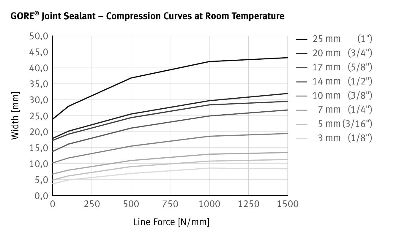
EN 13555 specifies a test flange that is DN 40 / PN 40 in size; therefore, GORE Joint Sealant DF05 was tested using a stiffness of 500 kN/mm. Results for all other sizes were extrapolated from DF05 results using the following compression curve.
Test Method
EN 13555 provides the test method for generating the gasket parameters used in EN 1591-1 calculations. The informative Annex G now provides some guidance for generating gasket design parameters for form-in-place products.
Due to the material properties of monoaxially expanded PTFE, the increase in the gasket width of GORE Joint Sealant depends on the pressure exerted on it. For the configuration and calculation of flange connections it is therefore easier to use line forces instead of gasket stress. The line force, Q*, is the ratio of the force per unit length.
Gasket Constant Definitions Modified for GORE Joint Sealant
| PQR | A measure of creep relaxation at a predefined temperature. It is the ratio between the gasket stress after relaxation and the initial gasket stress. The ideal PQR value is 1. The closer the test value is to the ideal value, the lower the loss of gasket stress of the seal. |
|---|---|
| Q*min(L) | The minimum required line force at ambient temperature for a certain leakage class L when the seal is first installed. |
| Q*Smin(L) | The minimum required line force for a certain leakage class L in service. |
| Q*Smax | The maximum line force that may be applied on the gasket, without damage or intrusion into the bore, at the indicated temperatures. It depends on the temperature and the seal thickness. |
| E*G | This describes the recovery (elastic behavior) of a seal at load reduction. It is related to the modulus of elasticity. It depends on the applied line force, the seal thickness and the temperature. |
General Test Method Description
| PQR | Creep Relaxation is measured at different temperatures, initial gasket stress, seal thickness values and flange stiffness values. The seal initially is exposed to the predefined gasket stress, then the temperature is increased and maintained for four hours. The residual gasket stress is then measured. |
|---|---|
| Q*min Q*Smin | A load is applied to and removed from the seal in predefined increments, with the leakage being measured constantly. The internal pressure is usually 40 bar (test gas: helium). |
| Q*Smax E*G | The gasket stress is increased cyclically and then reduced to 1/3 of the previous gasket stress. The seal thickness is then measured. The test is repeated at various temperatures. The E*G value is calculated from the load reductions and thickness changes. For Q*Smax, a sudden drop in seal thickness indicates failure. If a sudden drop occurs, the value of the loading step before failure is taken. In case no failure occurs, the maximum possible gasket stress of the test equipment is taken. The identified value is then used as the initial stress in a PQR test to verify the final Q*Smax under constant loading. |
Q*min [N/mm]
| L1,0 | L0,1 | L0,01 | L0,001 | |
|---|---|---|---|---|
| 3 mm (1/8") | 37 | 65 | 97 | 129 |
| 5 mm (3/16") | 50 | 90 | 140 | 190 |
| 7 mm (1/4") | 68 | 119 | 183 | 244 |
| 10 mm (3/8") | 104 | 183 | 286 | 381 |
| 14 mm (1/2") | 146 | 261 | 411 | 554 |
| 17 mm (5/8") | 179 | 315 | 506 | 678 |
| 20 mm (3/4") | 190 | 344 | 546 | 734 |
| 25 mm (1") | 276 | 513 | 832 | 1128 |
Q*Smin [N/mm]
| Q*A [N/mm] | QA [MPa] | L1,0 | L0,1 | L0,01 | L0,001 | |
|---|---|---|---|---|---|---|
| 3 mm (1/8") | 100 | 33 | 37 | 37 | x | x |
| 200 | 67 | 37 | 37 | 37 | 88 | |
| 300 | 100 | 37 | 37 | 37 | 50 | |
| 400 | 133 | 37 | 46 | 55 | 65 | |
| 5 mm (3/16") | 100 | 20 | 50 | 50 | x | x |
| 200 | 40 | 50 | 50 | 50 | 135 | |
| 300 | 60 | 50 | 50 | 50 | 70 | |
| 400 | 80 | 50 | 60 | 75 | 90 | |
| 7 mm (1/4") | 100 | 14 | 68 | 68 | x | x |
| 200 | 29 | 68 | 68 | 68 | 162 | |
| 300 | 43 | 68 | 68 | 68 | 92 | |
| 400 | 57 | 68 | 85 | 101 | 119 | |
| 10 mm (3/8") | 100 | 10 | 104 | 104 | x | x |
| 200 | 20 | 104 | 104 | 104 | 250 | |
| 300 | 30 | 104 | 104 | 104 | 143 | |
| 400 | 40 | 104 | 129 | 156 | 183 | |
| 14 mm (1/2") | 100 | 7 | 146 | 146 | x | x |
| 200 | 14 | 146 | 146 | 146 | 353 | |
| 300 | 21 | 146 | 146 | 146 | 202 | |
| 400 | 29 | 146 | 183 | 221 | 261 | |
| 17 mm (5/8") | 100 | 6 | 179 | 179 | x | x |
| 200 | 12 | 179 | 179 | 179 | 435 | |
| 300 | 18 | 179 | 179 | 179 | 248 | |
| 400 | 24 | 179 | 224 | 272 | 317 | |
| 20 mm (3/4") | 100 | 5 | 190 | 190 | x | x |
| 200 | 10 | 190 | 190 | 190 | 464 | |
| 300 | 15 | 190 | 190 | 190 | 265 | |
| 400 | 20 | 190 | 240 | 291 | 344 | |
| 25 mm (1") | 100 | 4 | 276 | 276 | x | x |
| 200 | 8 | 276 | 276 | 276 | 683 | |
| 300 | 12 | 276 | 276 | 276 | 390 | |
| 400 | 16 | 276 | 351 | 430 | 513 |
X: The leakage rate is not achieved at the pre-compression line force Q*A as part of the measuring program.
Q*Smax
| PQR @ QSmax | QSmax | Q*Smax 1 | Temperature | |
|---|---|---|---|---|
| 5 mm (3/16") | 0.97 | 200 MPa (29,010 psi) | 1000 N/mm | Room |
| 0.89 | 200 MPa (29,010 psi) | 1000 N/mm | 80 °C (212 °F) | |
| 0.92 | 200 MPa (29,010 psi) | 1000 N/mm | 150 °C (302 °F) |
1 Corresponds to inital gasket stress (initial width = 5 mm)
E*G
| EG | Gasket stress | Line force 1 | Temperature | |
|---|---|---|---|---|
| 5 mm (3/16") | 290 | 20 MPa (2,900 psi) | 100 N/mm | Room |
| 368 | 30 MPa (4,350 psi) | 150 N/mm | ||
| 438 | 40 MPa (5,800 psi) | 200 N/mm | ||
| 490 | 50 MPa (7,250 psi) | 250 N/mm | ||
| 527 | 60 MPa (8,700 psi) | 300 N/mm | ||
| 500 | 20 MPa (2,900 psi) | 100 N/mm | 80 °C (212 °F) | |
| 581 | 30 MPa (4,350 psi) | 150 N/mm | ||
| 671 | 40 MPa (5,800 psi) | 200 N/mm | ||
| 817 | 50 MPa (7,250 psi) | 250 N/mm | ||
| 971 | 60 MPa (8,700 psi) | 300 N/mm | ||
| 260 | 20 MPa (2,900 psi) | 100 N/mm | 150 °C (302 °F) | |
| 374 | 30 MPa (4,350 psi) | 150 N/mm | ||
| 380 | 40 MPa (5,800 psi) | 200 N/mm | ||
| 377 | 50 MPa (7,250 psi) | 250 N/mm | ||
| 369 | 60 MPa (8,700 psi) | 300 N/mm |
1 Corresponds to initial gasket stress (initial width = 5 mm)
Test Results
| m | 1.5 |
|---|---|
| y | 2500 |
Test Method
m & y are gasket constants used for flange design as specified in the ASME Boiler and Pressure Vessel Research Code Division 1 Section VIII Appendix 2. Leak Rates versus Y stresses and m factor for Gaskets is currently being proposed as a new test method in the ASTM F03 Working Group.
Gasket Constant Definitions
m, maintenance factor, is a factor that describes the amount of additional preload required to maintain the compressive load on a gasket after internal pressure is applied to a joint.
y, seating stress, is the minimum compressive stress (psi) required to achieve an initial seal.
Test Results
For GORE Joint Sealant in 2 mm thickness and with an internal pressure of 10 bar (145 psi), this results in:
| k1 | 10 • bD |
|---|---|
| k0KD | 18 MPa • bD |
| k0KDϑ | 200 MPa • bD temperature ϑ = 150 °C (302 °F) |
Test Method
There are no specific test standards for AD 2000 B 7 Gasket Parameters. However, an estimation is provided below. The 2015 edition of "AD 2000-Merkblatt B 7" refers to EN 13555 as a test standard(1) and uses table 9 from VDI 2200(2) for the conversion method. Please note that VDI 2200 states that such a conversion is invalid due to the different measurement methods. "Only the method according to DIN EN 1591-1 and AD 2000 in conjunction with DIN EN 1591-1 and FE analysis can be used for providing stability and leak tightness." (3)
Gore supports the use of the AD 2000-Merkblatt B 7 and provides the necessary gasket parameters below.
There are the following relations(1):
k0KD ≙ Qmin · bD
k1 ≙ (QSmin / p) · bD since m ≙ QSmin / p (4)
k0KDϑ ≙ Qsmax · bD
| Qmin | minimum required gasket stress at ambient temperature when the seal is first installed (based on EN13555) |
|---|---|
| QSmin | minimum required gasket stress in service (based on EN13555) |
| QSmax | maximum gasket stress that may be applied on the gasket at an indicated temperature ϑ (based on EN 13555) |
| bD | width of the gasket |
| p | internal pressure of the media |
| k1 | AD 2000 B7 gasket parameter for service condition |
| k0KD | AD 2000 B7 gasket parameter for gasket deformation |
| k0KDϑ | AD 2000 B7 gasket parameter for gasket deformation in service at temperature ϑ |
If necessary for a specific application, Gore recommends doing individual conversions based on data from EN 13555.
The use of the general values given in table 1 of AD 2000-Merkblatt B 7(5) is not broadly recommended. However they may be applicable depending on the given situation.
Please also note that the quoted standards of DIN 2690 to DIN 2692 were superseded by EN 1514-1 in 1997.
(1) Arbeitsgemeinschaft Druckbehälter: AD 2000-Merkblatt B 7, Berechnung von Druckbehältern, Schrauben, Seite 4, 7.1.2.4, April 2015
(2) Verein Deutscher Ingenieure e. V.: VDI 2200, Tight flange connections - Selection, calculation, design and assembly of bolted flange connections, page 36, table 9, June 2007
(3) Verein Deutscher Ingenieure e. V.: VDI 2290, Emission Control - Sealing constants for flange connections, page 8, June 2012
(4) Please note that factor m = QSmin / p was defined by DIN V 2505 which was superseded by EN 1591-1 where m is no longer used
(5) Arbeitsgemeinschaft Druckbehälter: AD 2000-Merkblatt B 7, Berechnung von Druckbehältern, Schrauben, Seite 6, Tabelle 1, April 2015
Certificates & Application Information
| Type | Description | File |
|---|---|---|
| Oxygen Service (BAM) | The Federal Institute for Materials Research and Testing (BAM) tests the sealing material compatibility for use in flanged connections with liquid and gaseous oxygen. Further information on the test procedure and the result can be found in the following test report. | Download |
| Chlorine Service | Eurochlor's publication on Experience of Gaskets in Liquid Chlorine and Dry or Wet Chlorine Gas Service and the Chlorine Institute's Pamphlet 95 Gaskets for Chlorine Service cover gaskets for both dry and wet chlorine service and highlight materials that have found user acceptance through field-testing and member company experience. GORE GR Sheet Gasketing and GORE Universal Pipe Gasket (Style 800) are both listed in these publications. The documents are available from the respective organizations. | |
| Leachable Fluoride and Chloride | This test analyzes leachable water-soluble fluoride and chloride ions which can induce flange corrosion. The samples are leached for 24 hours at approximately 95 °C in demineralized water. Contact Gore for further information if this testing is required for your application. | |
| Safety Information | GORE Gasketing products meet the definition of an article; therefore, a Material Safety Data Sheet (MSDS) or Safety Data Sheet (SDS) is not required. However, for your convenience, a Product Safety Sheet, which details the intended use and proper handling of our articles, is provided. | Download |
| Gore Quality Management System | The Gore Sealant Technologies Quality Management System is certified in accordance with ISO 9001. |
Featured Content
Explore More

FOR INDUSTRIAL USE ONLY
Not for use in food, drug, cosmetic or medical device manufacturing, processing, or packaging operations.
Prefer to Call?
Have questions or unique requirements?
Our experts are here to guide you.