GORE® Microwave RF Assemblies, Vapor Sealed
With a durable, more flexible construction, our assemblies are proven to keep out water, vapor, fuel and other harsh aircraft contaminants for longer service life.
Vapor-Sealed Assemblies Provide Durable Performance
GORE® Microwave RF Assemblies are not only vapor-sealed but also provide outstanding shielding effectiveness against EMI that can compromise signal quality and transmission. They routinely maintain low loss and excellent phase stability up to 40 GHz for longer system life, less downtime and reduced total costs.
Improved Mechanical & Electrical Performance
The vapor-sealed version of GORE Microwave RF Assemblies features approved aerospace materials and offers many benefits that improve their overall system performance, like:
- durable vapor barrier prevents ingress of water, vapor and hash contaminants
- maintains quality signals with low loss and excellent phase stability up to 40 GHz
- less RF interference due to outstanding shielding effectiveness
- easier installation with smaller diameters, more flexibility and tighter bend radii
- longer system life for reduced aircraft downtime and lower total costs
- meets stringent industry standards, like MIL-T-81490 and others (Contact Gore for available data)
- increased design flexibility with robust, replaceable connector options

Military Airborne Applications
Vapor-sealed GORE Microwave RF Assemblies provide superior mechanical protection and electrical performance in military airborne applications, like:
- active electronically scanned array (AESA) radar
- electronic defensive systems (signal detection, interception, identification)
- SATCOM antennas

Commercial Airborne Applications
Our vapor-sealed assemblies also perform reliably in a variety of commercial airborne applications, like:
- active electronically steered phase arrays
- GPS connectivity
- Iridium telecom satellites
- Ku-Band SATCOM antennas
- L-Band Air-to-Ground (ATG) networks
- Swift Broadband
Technical Information
These values demonstrate the electrical, mechanical and environmental performance of vapor-sealed GORE Microwave RF Assemblies for defense and civil aircraft.
Elec./Mech./Environ. Property
| Value | ||||
|---|---|---|---|---|---|
Type 7G | Type 75 | Type 7E | Type 7L | Type 7M | |
Max Frequency GHz | 40.0 | 18.0 | 18.0 | 7.0 | 2.0 |
Typical VSWR through Max Frequency (straight connector) | 1 30:1 | 1 25:1 | 1 25:1 | 1 20:1 | 1 10:1 |
Typical Insertion Loss at Max Frequency dB/ft. (dB/m) | 0.78 (2.56) | 0.32 (1.05) | 0.19 (0.62) | 0.10 (0.33) | 0.04 (0.13) |
Standard Impedance Ohms | 50 ± 1 | 50 ± 1 | 50 ± 1 | 50 ± 1 | 50 ± 1 |
Nominal Dielectric Constant | 1.4 | 1.4 | 1.4 | 1.4 | 1.4 |
Nominal Velocity of Propagation % | 85 | 85 | 85 | 85 | 85 |
Nominal Time Delay ns/in (ns/m) | 3.94 (1.2) | 3.94 (1.2) | 3.94 (1.2) | 3.94 (1.2) | 3.94 (1.2) |
Shielding Effectiveness through Max Frequency db | > 90 | > 90 | > 90 | > 90 | > 90 |
Jacket Material | Engineered Fluoropolymer or PFA | Engineered Fluoropolymer or PFA | Engineered Fluoropolymer or PFA | Engineered Fluoropolymer or PFA | Engineered Fluoropolymer or PFA |
Jacket Color | EF: Black, | EF: Black, | EF: Black, | EF: Black, | EF: Black, |
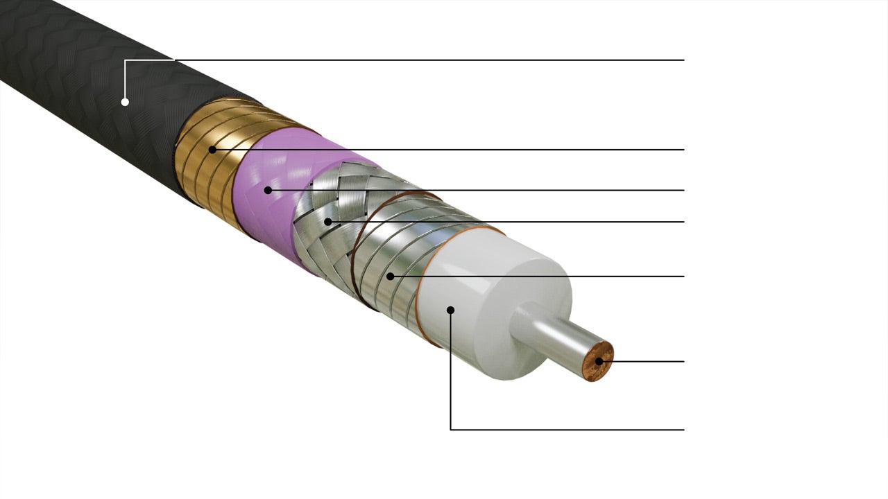
Center Conductor | Solid SPC | Solid SPC | Solid SPC | Stranded SPC | Solid SPC |
Dielectric Material | Expanded PTFE | Expanded PTFE | Expanded PTFE | Expanded PTFE | Expanded PTFE |
Nominal Outer Diameter in (mm) | 0.150 (3.80) | 0.210 (5.30) | 0.335 (8.50) | 0.485 (12.32) | 0.565 (14.35) |
Nominal Weight oz./ft. (g/m) | 0.39 (36) | 0.67 (63) | 1.61 (150) | 2.82 (262) | 3.52 (328) |
Minimum Bend Radius in (mm) | 0.75 (19.0) | 1.0 (25.0) | 2.0 (50.0) | 2.5 (62.5) | 3.15 (80.0) |
Temperature Rangea °C | -58 to +200 | -58 to +200 | -58 to +200 | -58 to +200 | -58 to +200 |
Concentrated Load lbs./in (kgf/cm) | 50 (8.95) | 50 (8.95) | 50 (8.95) | 50 (8.95) | 50 (8.95) |
a. For applications operating above 175°C, contact a Gore representative.
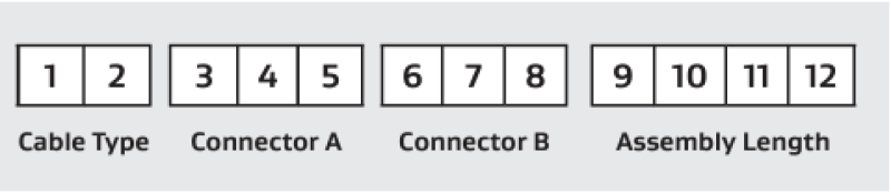
Vapor-sealed GORE Microwave RF Assemblies are identified by a 12-character part number designating the cable type, connector types, and assembly lengths.
Positions 1–2: Two-character code representing each cable type (e.g., 7G, 75, 7E, 7L, 7M).
Positions 3–5: Connector A that attaches to the left side of the cable assembly.
Positions 6–8: Connector B that attaches to the right side of the cable assembly.
Positions 9–12: The assembly length is expressed in inches to the nearest tenth, including zeroes to fill positions if the length is less than three digits. For example, the length of a 24-in assembly is specified as 0240 in the last four digits of the part number.
Example part numbers for our cable types include the following:
7E7V18013205
75C02C710122
75C01C010901
75R01R010480
7EC01C010590
7EC0LR015880
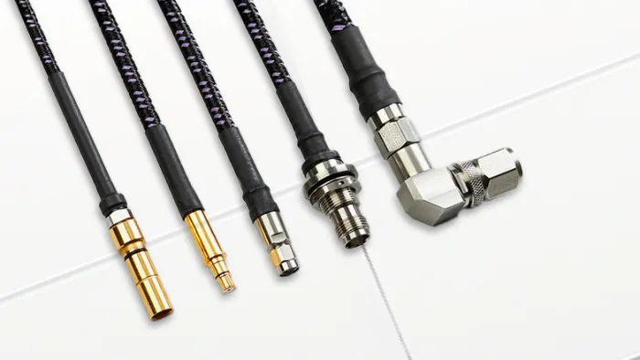
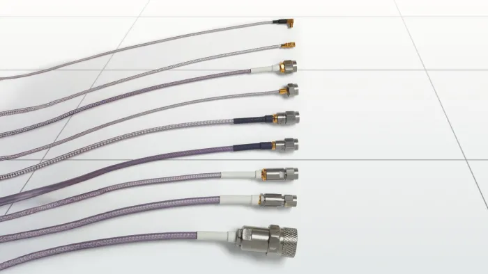
Connector Options
For all of our cable types, we offer a variety of connector options specifically designed to optimize the performance of each assembly, like SMA, TNCA and more. We also offer an interface that allows the use of replaceable connectors.
Featured Content


Explore More

FOR INDUSTRIAL USE ONLY
Not for use in food, drug, cosmetic or medical device manufacturing, processing, or packaging operations.
Prefer to Call?
Have questions or unique requirements?
Our experts are here to guide you.