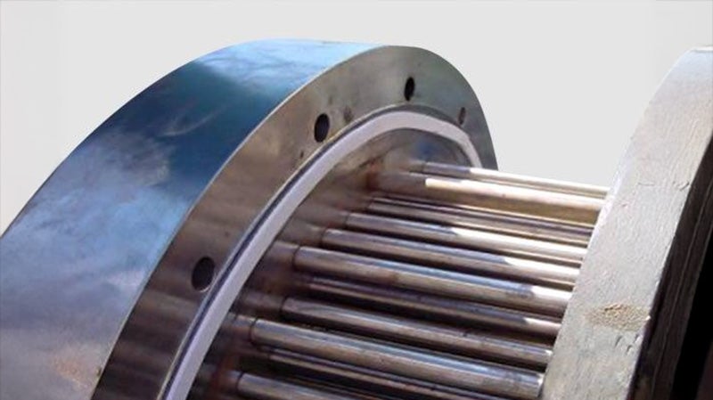
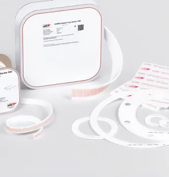
GORE® Gasket Tape Series 500 for Large Steel Flanges
This exceptionally creep-resistant 100% ePTFE form-in-place gasket tape delivers worry-free high-temperature sealing performance in large steel flanges.
High Temperature Gasket Tape: Reliable Performance and Extended Durability
Sealing large steel flanges in industrial or chemical processing operations can be complicated: factors like aggressive media, thermal cycling, uneven or corrosion-damaged sealing surfaces can compromise seal durability and longevity. While one-piece prefabricated gaskets can be an option, it can be a costly one: as well as price, there can be long lead-times and supply-chain issues to consider.
Expanded PTFE Gasket Tape
A spool of GORE® Gasket Tape Series 500 provides an immediate, cost-effective solution to sealing challenges that demand reliable performance and extended durability. This high-temperature gasket tape, with its industry-leading creep resistance, is designed to maximize the operational reliability of large-diameter steel flange applications, especially those with thermal cycling.
Heat Resistant Gasket Tape that Fits Any Shape and Creates a Tight, Long-Lasting Seal
Save time, money, and trouble with this cutting-edge form-in place product that maximizes operational reliability of large steel pipe and equipment flanges.
GORE Gasket Tape Series 500:
- Is made of chemically inert 100% ePTFE, making it versatile enough for use in strong alkali-, acid- and solvent-based process systems
- Durably withstands the rigors of harsh chemical processes as it resists all process media (pH 0-14) except molten/dissolved alkali metals and elemental fluorine
- Delivers dramatically improved creep resistance
- Forms a very tight seal that is long-lasting while also handling the rigors of virtually any chemical process
- Fits any shape instantly, which eliminates large-gasket fabrication and inventory challenges
- Eliminates the lag time, costs and complexities associated with engineering, specifying, procuring, shipping, storing and installing traditional one-piece prefabricated gaskets.
GORE Gasket Tape Series 500 excels at maintaining seal integrity on large steel flanges, even when exposed to high temperatures or thermal cycling.
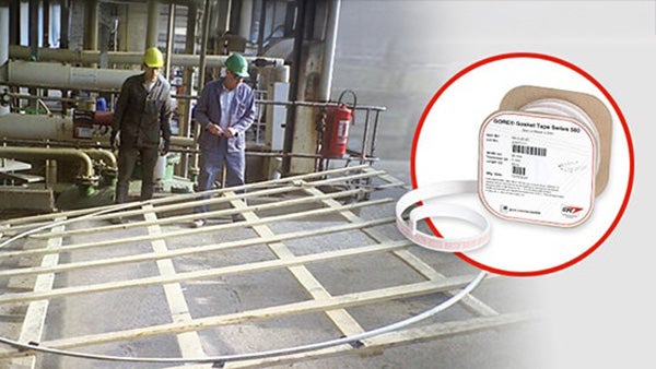
GORE Gasket Tape Series 500 is a time- and cost-saving alternative to ordering, storing and installing very large one-piece gaskets.
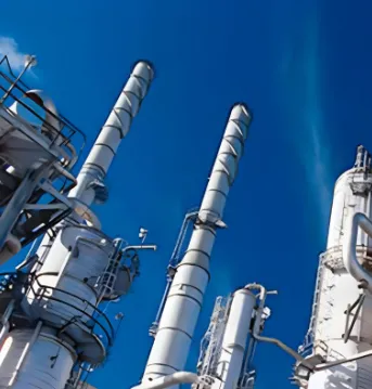
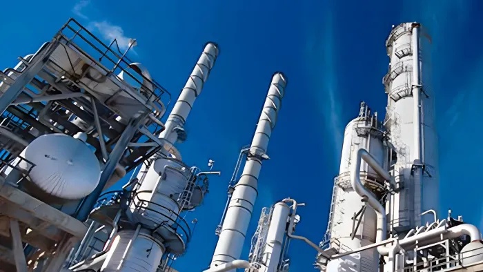
Maximize Operational Reliability of Large-Diameter Steel Flange Applications
High temperature gasket tape is ideal for large steel flanges in any processes involving thermal cycling — that is, processes with inherently variable and/or extreme operating temperature ranges. Thermal cycling affects the coefficient of expansion of the steel flanges and bolt-loads, and as well as the cold-flow and creep properties of the surrounding gaskets. Therefore, processes that involve thermal cycling require a gasket designed to withstand them, in order to maintain the integrity of the seal.
Processes involving highly aggressive media or thermal cycling:
- Chemical processing
- Pulp and paper manufacturing
- Mining and minerals
- Semiconductor manufacturing
- Power generation
Large and/or non-standard steel equipment flanges:
- Vessel and tank process flanges & manways
- Large-diameter piping
- Heat exchangers
- Baffles
- Non-Standard flanges (rectangular)
Why Gore’s High Temperature Gasket Tape Outperforms Ordinary PTFE Gasket Tape
Proprietary manufacturing technology
GORE Gasket Tape Series 500 is made of 100% expanded polytetrafluoroethylene (ePTFE), using a proprietary Gore manufacturing technology that creates a high-temp gasket tape with exceptional sealing reliability, especially on large and irregularly shaped steel flanges.
The expansion of PTFE adds creep resistance and better cold flow resistance, which enables the material to withstand high-temperature applications.
High-temperature sealant tape
GORE Gasket Tape Series 500 is typically used in applications with a temperature range of -60 °C to 230 °C (-76 °F to 445 °F) up to 40 bar (580 psi). If your high-temp flange gasket must withstand non-typical temperature/pressure ranges, contact us for guidance and recommendations.
Almost twice as creep-resistant
Because of its internal structure, GORE Gasket Tape Series 500 excels at resisting cold flow and creep. Tests prove GORE Gasket Tape Series 500 is nearly twice as effective at resisting creep than other brands of ePTFE gasket tape.
GORE Gasket Tape Series 500 is almost twice as creep-resistant as other ePTFE gasket tapes. (Data based on EN13555.)
Sealability Proof of the Skive Joint
This video demonstrates the tight, reliable seal — even around skive joints — that is created with GORE Gasket Tape Series 500.
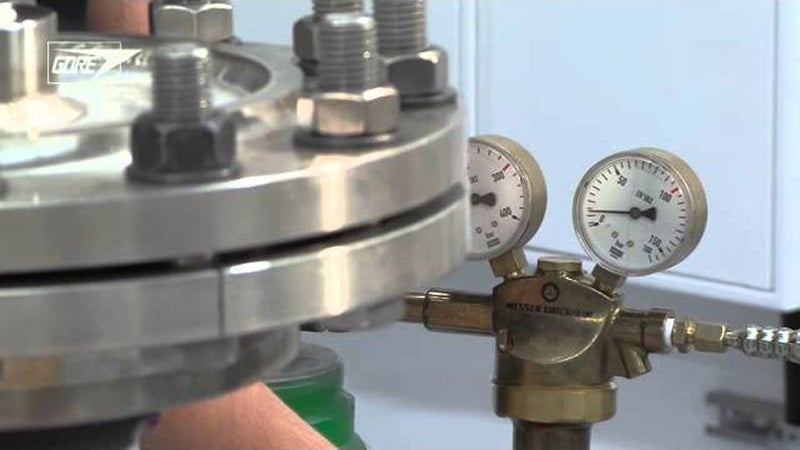
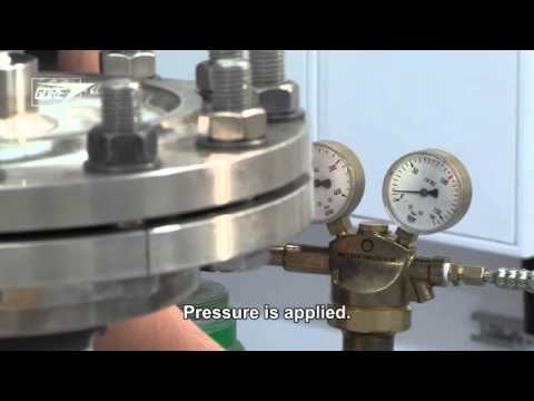
Superior Tightness vs One-Piece Gaskets
This video demonstrates the superior tightness of a GORE Gasket Tape Series 500 seal versus that of one-piece gaskets.
Technical Information
Material |
|
Chemical Resistance | Chemical resistance to all media pH 0-14, except molten alkali metals and elemental fluorine. |
Operating Range | The maximum applicable pressure and temperature depend mainly on the equipment and installation.
For applications outside the typical use range, Gore recommends an application specific engineering design calculation and extra care during installation. Also, consider retorquing after a thermal cycle when the equipment has returned to an ambient temperature condition. Please contact Gore if further guidance is required. |
Shelf Life | Expanded PTFE is not subject to aging and can be stored indefinitely. To ensure optimal adhesive function, we recommend use within two years of date of purchase when stored under normal(2) conditions |
(1) absolute pressure of 1 mmHg (Torr) = 133 Pa = 1.33 mbar = 0.019 psi
(2) 21 °C (70 °F) 50% Relative Humidity
GORE® Gasket Tape Series 500 is available in all listed width and thickness combinations, and multiple spool lengths.
Parts are manufactured to metric dimensions.
Width | Thickness |
10 mm (3/8") | 3 mm (1/8”) |
15 mm (1/2") | |
20 mm (3/4") | |
25 mm (1") | |
30 mm (1.25") | |
40 mm (1.5") | |
50 mm (2") |
Test Data
| Test Temperature | Thickness | ||
|---|---|---|---|
| 3 mm (1/8") | 6 mm (1/4") | ||
| Creep Relaxation | 23 °C (73 °F) | 5% | 10% |
| 169 °C (336 °F) | 43% | 54% | |
Based on EN 13555, this testing was conducted with a fixture stiffness of 500 kN/mm, at the minimum stress to seal, using 30 mm wide strips.
Thickness | ||
|---|---|---|
| 3 mm (1/8") | 6 mm (1/4") | |
| Minimum stress to seal to achieve a 0.1 mg/(s·m) nitrogen leak rate | 19 MPa (2,755 psi) | 23 MPa (3,335 psi) |
This testing was conducted using 30 mm wide tape formed into a circle of 230 mm diameter.
Test Results
Thickness | Exposure Temperature | Initial Gasket Stress | Test Step 1 | Test Step 2 | |
|---|---|---|---|---|---|
VDI 2200 (06-2007) | 3.0 mm | 230 °C | 30 MPa | Yes, 60 bar | Yes, 60 bar |
Test Method Overview
The aim of the VDI guideline is to analyze and organize the applicable seal connection conditions based on the technical standard, to complete the conditions, including latest research results, and advise the user in selection, interpretation, design, and assembling of flange joints in particular consideration of the gaskets. The blowout safety test of seals in sealing systems with even flanges corresponds with the current state of test engineering. The seal itself cannot accomplish blowout safety. It always depends on the entire system of the flange joint.
General Test Procedure
- Installation of seal with installation surface pressure in four steps (25 %, 50 %, 75 % and 100 % of bolt force through crosswise tightening). Installation surface pressure and seal thickness are to be indicated in the test record. The lift-off force, caused by the nominal pressure, referring to the middle seal diameter, shall additionally be considered in all testing steps.
- Retightening to installation surface pressure after 5 minutes.
- Flange heating to temperature with 2 K/min in recirculation furnace or using inside heated cartridges.
- Maintenance of thermal storage temperature for minimum 48 hours.
- Cooling down of the flange to ambient temperature.
- Measurement of the remaining surface pressure.
Test Step 1
The blowout safety test is performed with nitrogen up to the 1.5-fold of the nominal pressure. Tests with higher pressures are allowed, if required. The internal pressure is to be increased stepwise, in steps of 5 bar to the above-mentioned pressure. The holding period per pressure stage amounts to a minimum of 2 min.
As "blowout" is defined, if, within 5 s, a pressure decay of Δp ≥ 1 bar· (V0 = test room volume) is exceeded. The achieved internal pressure is to be indicated in the test record. If blowout did not occur until the maximum test pressure, the test is to be continued according to test step 2.
Test Step 2
The internal pressure is discharged, and the surface pressure is reduced to 5 N/mm with regard to lifting force caused by the internal pressure. Variations of the surface pressure are to be stated in the testing report."
Source: Verein Deutscher Ingenieure e. V.: VDI2200: Tight flange connections - Selection, calculation, design and assembly of bolted flange connections, June 2007, page 4
Source: ibidem, page 64
Test Temperature | Thickness | ||
|---|---|---|---|
3 mm (1/8") | 6 mm (1/4") | ||
Maximum Surface Stress | Ambient | 170 MPa | 160 MPa |
Based on EN 13555, this testing was conducted using a 65 mm x 85 mm ring gasket.
Gasket Design Factors
Gasket Constant Definitions
PQR | A measure of creep relaxation at a predefined temperature. It is the ratio between the gasket stress after relaxation and the initial gasket stress. The ideal PQR value is 1. The closer the test value is to the ideal value, the lower the loss of gasket stress. |
Qmin(L) | The minimum required gasket stress at ambient temperature for a certain leakage class L when the seal is first installed. |
QSmin(L) | The minimum required gasket stress for a certain leakage class L in service. |
QSmax | The maximum gasket stress that may be applied on the gasket, without damage or intrusion into the bore, at the indicated temperatures. It depends on the temperature and the gasket thickness. |
EG | The recovery (elastic behavior) of a seal at load reduction and is related to the modulus of elasticity. It depends on the applied gasket stress, the seal thickness and the temperature. |
General Test Method
PQR | Creep Relaxation is measured at different temperatures, initial gasket stress, seal thickness values and flange stiffness values. The seal initially is exposed to the predefined gasket stress, then the temperature is increased and maintained for four hours. The residual gasket stress is then measured. |
Qmin | A load is applied to and removed from the seal in predefined increments, with the leakage being measured constantly. The internal pressure is usually 40 bar (test gas: helium). |
QSmax | The gasket stress is increased cyclically and then reduced to 1/3 of the previous gasket stress. The seal thickness is then measured. The test is repeated at various temperatures. The EG value is calculated from the load reductions and thickness changes. For QSmax, a sudden drop in seal thickness indicates failure. If a sudden drop occurs, the value of the loading step before failure is taken. In case no failure occurs, the maximum possible gasket stress of the test equipment is taken. The identified value is then used as the initial stress in a PQR test to verify the final QSmax under constant loading. |
Thickness | 3 mm (1/8") | 6 mm (1/4") |
m | 2.5 | 2.5 |
y | 2,750 psi | 3,330 psi |
This testing was conducted using 30 mm wide tape formed into a circle of 230 mm diameter.
m & y are gasket constants used for flange design as specified in the ASME Boiler and Pressure Vessel Research Code Division 1 Section VIII Appendix 2. Leak Rates versus Y stresses and m factor for Gaskets is currently being proposed as a new test method in the ASTM F03 Working Group.
Gasket Constant Definitions
m, maintenance factor, is a factor that describes the amount of additional preload required to maintain the compressive load on a gasket after internal pressure is applied to a joint.
y, seating stress, is the minimum compressive stress (psi) required to achieve an initial seal.
For GORE Gasket Tape Series 500 in 3 mm thickness and with an internal pressure of 40 bar (580 psi), this results in:
k1 | 2.5 · bD |
k0KD | 22 MPa · bD |
k0KDϑ | 120 MPa · bD temperature ϑ = 230 °C (446 °F) |
There are no specific test standards for AD 2000 B 7 Gasket Parameters. However, an estimation is provided below. The 2015 edition of "AD 2000-Merkblatt B 7" refers to EN 13555 as a test standard(1) and uses table 9 from VDI 2200(2) for the conversion method. Please note that VDI 2200 states that such a conversion is invalid due to the different measurement methods. "Only the method according to DIN EN 1591-1 and AD 2000 in conjunction with DIN EN 1591-1 and FE analysis can be used for providing stability and leak tightness."(3)
Gore supports the use of the AD 2000-Merkblatt B 7 and provides the necessary gasket parameters below.
There are the following relations(1):
k0KD ≙ Qmin · bD
k1 ≙ (QSmin / p) · bD since m ≙ (QSmin / p)(4)
k0KDϑ ≙ QSmax · bD
Qmin | minimum required gasket stress at ambient temperature when the seal is first installed (based on EN 13555) |
QSmin | minimum required gasket stress in service (based on EN 13555) |
QSmax | maximum gasket stress that may be applied on the gasket at an indicated temperature ϑ (based on EN 13555) |
bD | width of the gasket |
p | internal pressure of the media |
k1 | AD 2000 B 7 gasket parameter for service condition |
k0KD | AD 2000 B 7 gasket parameter for gasket deformation |
k0KDϑ | AD 2000 B 7 gasket parameter for gasket deformation in service at temperature ϑ |
If necessary for a specific application, Gore recommends to do individual conversions based on data from EN 13555.
If necessary for a specific application, Gore recommends to do individual conversions based on data from EN 13555.
The use of the general values given in table 1 of AD 2000-Merkblatt B 7(5) is not broadly recommended. However they may be applicable depending on the given situation.
Please also note that the quoted standards of DIN 2690 to DIN 2692 were superseded by EN 1514-1 in 1997.
(1)Arbeitsgemeinschaft Druckbehälter: AD 2000-Merkblatt B 7, Berechnung von Druckbehältern, Schrauben, Seite 4, 7.1.2.4, April 2015.
(2)Verein Deutscher Ingenieure e. V.: VDI 2200, Tight flange connections - Selection, calculation, design and assembly of bolted flange connections, page 36, table 9, June 2007.
(3)Verein Deutscher Ingenieure e. V.: VDI 2290, Emission Control - Sealing constants for flange connections, page 8, June 2012.
(4)Please note that factor m = QSmin / p was defined by DIN V 2505 which was superseded by EN 1591-1 where m is no longer used.
(5)Arbeitsgemeinschaft Druckbehälter: AD 2000-Merkblatt B 7, Berechnung von Druckbehältern, Schrauben, Seite 6, Tabelle 1, April 2015.
Certifications & Application Information
| Type | Description | File |
|---|---|---|
| Oxygen Service (BAM) | The Federal Institute for Materials Research and Testing (BAM) tests the sealing material compatibility for use in flanged connections with liquid and gaseous oxygen. Further information on the test procedure and the result can be found in the following test report. Please note that the test was conducted without adhesive backing. | Download PDF |
Leachable Fluoride and Chloride | This test analyzes leachable water-soluble fluoride and chloride ions which can induce flange corrosion. The samples are leached for 24 hours at approximately 95 °C in demineralized water. Contact Gore for further information if this testing is required for your application. | |
| Safety Information | GORE® Gasketing products meet the definition of an article; therefore, a Material Safety Data Sheet (MSDS) or Safety Data Sheet (SDS) is not required. However, for your convenience, a Product Safety Sheet (PSS), which details the intended use and proper handling of our articles, is provided below. | Download PDF |
| Gore Quality Management System | The Gore Sealant Technologies Quality Management System is certified in accordance with ISO 9001. |
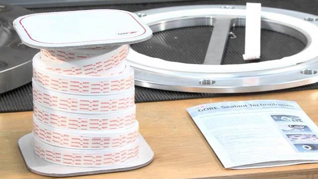
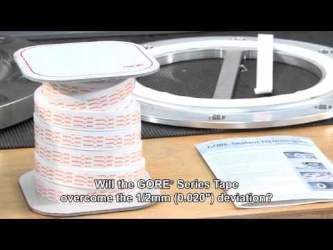
Conformability Case History
Related Content
Explore More


FOR INDUSTRIAL USE ONLY
Not for use in food, drug, cosmetic or medical device manufacturing, processing, or packaging operations.
Prefer to Call?
Have questions or unique requirements?
Our experts are here to guide you.