Part Number Information: GORE® Microwave / RF Assemblies
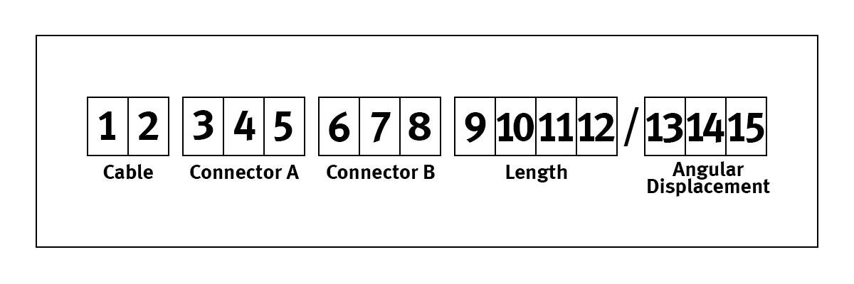
Part numbers consist of 12 alphanumeric characters. The grouping of these characters has a specific meaning. The part number includes cable type, connector types, and assembly length.
- Characters 1 and 2 designate cable type.
- Characters 3-5 define connector “A” and Characters 6-8 define connector “B”.
- Characters 9-11 define the assembly length in inches.* Character 12 is used to further define lengths which are not whole-inch increments. If the length is a whole-inch increment, Character 12 should be zero. Even foot increments are standard; for example, the standard lenghth closest to 3 meters is 10 feet (120.0 inches)
*PLEASE NOTE: Gore's VNA Microwave Test Assemblies are available in three lengths: 25 inches, 38 inches, and 48 inches.
If other lengths are required, consider GORE® PHASEFLEX® Microwave / RF Test Assemblies as an alternative.
Cable Types and Descriptions
FB Microwave Test Assemblies
- Ruggedized 7 mm, 3.5 mm, and Precision N connectors
- Designed to mate directly with network analyzers
- Mode-free, broadband coaxial measurements up to 26.5 GHz
FD Microwave Test Assemblies
- Ruggedized 2.92 mm (K style) connectors
- Designed to mate with ruggedized 2.92 mm pin ports on network analyzers
- Mode-free, broadband coaxial measurements up to 40 GHz
FE Microwave Test Assemblies
- Ruggedized 2.4 mm connectors
- Designed to mate directly to the 2.4 mm pin port connector on network analyzers
- Mode-free, broadband coaxial measurements up to 50 GHz
FF Microwave Test Assemblies
- Ruggedized 1.85 mm (V-style) connectors
- Designed to mate directly to the ruggedized 1.85 mm pin port on network analyzers
- Mode-free, broadband coaxial measurements up to 67 GHz
Connector Types
Connector options include Precision N, 7 mm, 3.5 mm, 2.92 mm, 2.4 mm and 1.85 mm.
| Gore VNA Microwave Test Assemblies | Connector Type | Description | Fmax (GHz) | Cable FB 26.5 | Cable FD 40 | Cable FE 50 | Cable FF 67 |
|---|---|---|---|---|---|---|---|
| END A | 7 mm | Hermaphrodatic | 18 | 0HD | 0HD | 0HD | |
| END A | 3.5 mm | NMD port socket | 26.5 | 0HA | |||
| END A | 2.92 mm | NMD port socket | 40 | 0BS | |||
| END A | 2.4 mm | NMD port socket | 50 | 0BN | |||
| END A | 1.85 | NMD port socket | 67 | 0CN | |||
| END B | Precision N | Pin | 18 | 0AH | 0AH | 0AH | |
| END B | Precision N | Socket | 18 | 0AL | 0AL | 0AL | |
| END B | 7 mm | Hermaphrodatic | 18 | 0HD | 0HD | 0HD | |
| END B | 3.5 mm | NMD DUT pin | 26.5 | 0HB | 0HB | 0HB | |
| END B | 3.5 mm | Socket | 26.5 | 0HC | 0HC | 0HC | |
| END B | 2.92 mm | NMD DUT pin | 40 | 0HR | 0HR | ||
| END B | 2.92 mm | Socket | 40 | 0HQ | 0HQ | ||
| END B | 2.4 mm | NMD DUT pin | 50 | 0BM | |||
| END B | 2.4 mm | Socket | 50 | 0BL | |||
| END B | 1.85 mm | NMD DUT pin | 67 | 0CM | |||
| END B | 1.85 mm | Socket | 67 | 0CL |
The pictures below illustrate an example of each connector type and description. The photos representing 3.5mm, 2.92mm, 2.4mm and 1.85mm connectors are of 3.5mm connectors; however, all connectors are of similar general appearance and will mate to analyzers and cables within the same connector family.
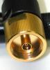
Ruggedized Port Socket
Part Numbers: 0HA, 0BS, 0BN, and 0CN
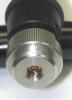
Ruggdized DUT Pin
Part Numbers: 0HB, 0HR, 0BM, and 0CM
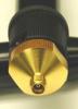
DUT Socket
Part Numbers: 0HC, 0HQ, 0BL, and 0CL
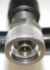
Precision N Pin
Part Numbers: 0AH
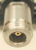
Precision DUT Socket
Part Numbers: 0AL

7mm Hermaphroditic
Part Numbers: 0HD
FOR INDUSTRIAL USE ONLY
Not for use in food, drug, cosmetic or medical device manufacturing, processing, or packaging operations.