GORE® Microwave RF Assemblies, General Purpose
Our small, flexible assemblies deliver stable electrical performance in many application and testing environments across industries for fewer replacements and less total costs.
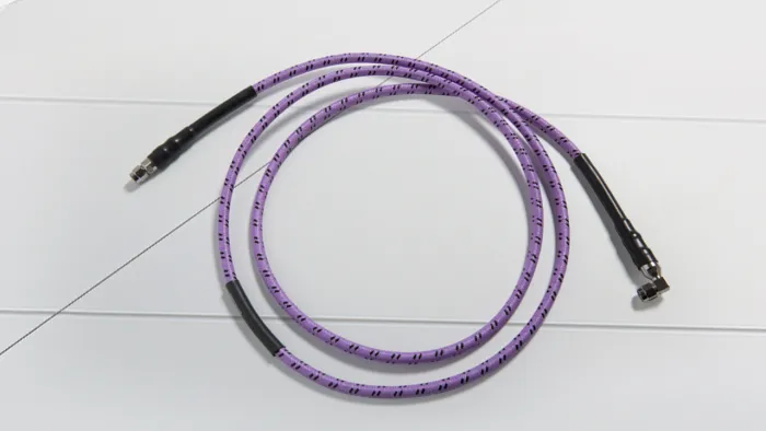
Maximum Flexibility, Excellent Electrical Performance
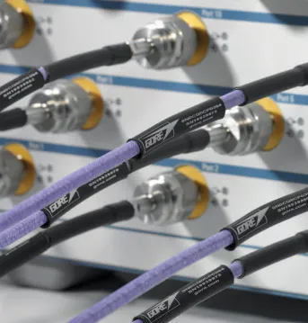
GORE® Microwave RF Cable Assemblies offer small, light, flexible general purpose options up to extremely high frequencies (EHF). Our low-loss coaxial cables are proven to maintain excellent electrical performance and shielding effectiveness with phase and amplitude stability over time. They’re easier to handle and hold up to tight routing compared to RF or semi-rigid cables.
Consistent Performance Over Time
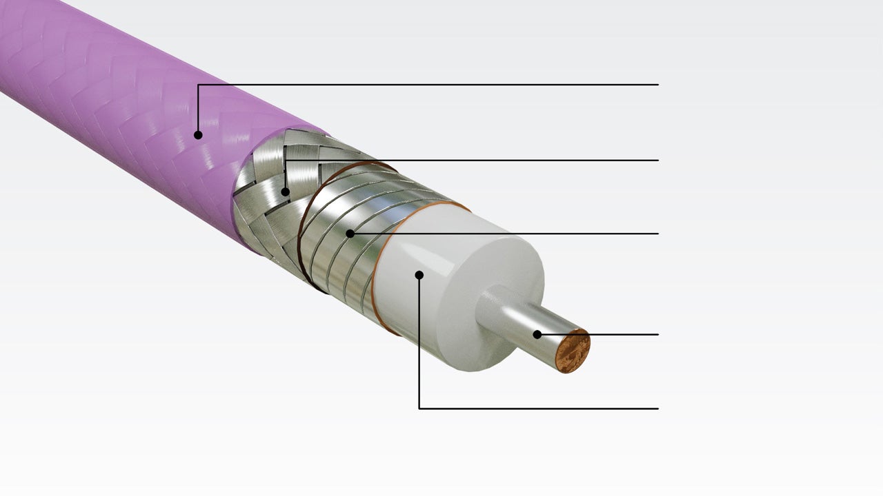
GORE Microwave RF Assemblies, general purpose, are engineered with unique mechanical features, including:
- chemically inert, temperature-stable layers
- EMI shielding materials
- Smaller, lighter, extremely flexible diameters
Our assemblies deliver performance benefits that manufacturers and end users across industries can trust and rely on, like:
- excellent signal integrity up to 70 GHz during installation and over time
- precise, repeatable test measurements with consistent phase and amplitude stability
- low insertion loss, more reliable VSWR and outstanding shielding effectiveness
- survive rigorous handling and routing than traditional RG or semi-rigid cables
- easier routing with more flexibility and tight bending down to 0.10 in (2.54 mm)
- improved aircraft fuel efficiency and more payload with lightweight assemblies
- less maintenance, reduced system downtime and lower total ownership cost
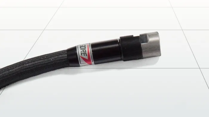
- more design options with a variety of robust, low-profile connector options

Proven Reliability Across Industries
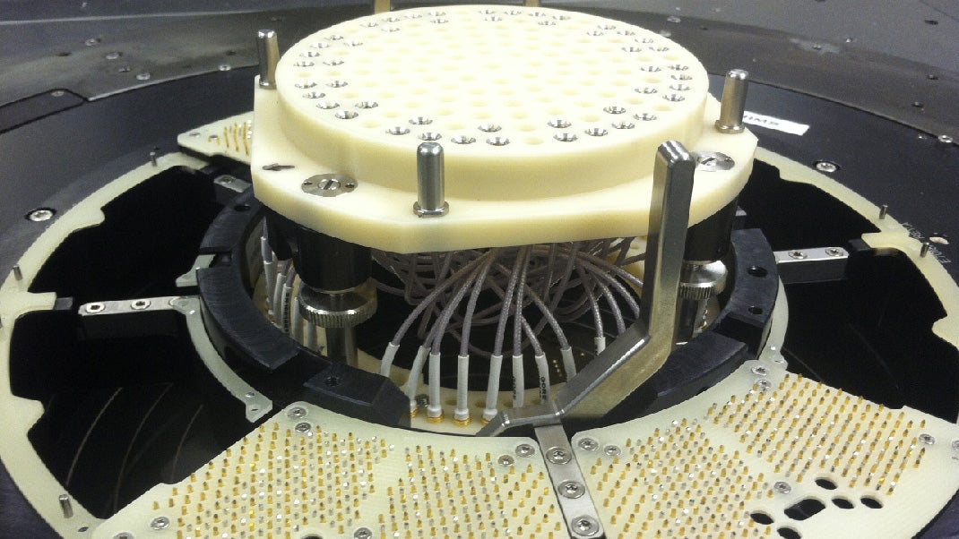
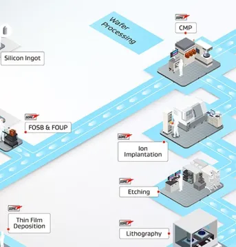
GORE Microwave RF Assemblies perform reliably in many general purpose applications across industries — including aerospace and defense, semiconductor, and test and measurement.
- 5G test & interconnection
- antenna arrays
- automated test equipment (ATE)
- backplane interconnects
- between-the-box connections
- board-to-board systems
- clock distribution
- evaluation & load boards
- environmental test chambers
- inside-the-box systems
- module-to-module interconnects
- optical modules
- RF lab testing
- telecommunication systems
- test bench systems
- thermal vacuum (TVac) chambers
For in-the-lab and flight-line RF testing and environmental test chambers, we recommend rugged GORE® PHASEFLEX® Microwave/RF Test Assemblies.
For critical military and commercial aircraft systems, our flexible, electrically stable RF cable assemblies are often used and trusted in:
- C5ISR suites
- airborne electronic surveillance, countermeasures & jamming
- electronic warfare (EW) systems
- radar warning receiver (RWR) systems
- radar interconnects
- electronic & signal intelligence
- navigation & communications systems
- millimeter wave (mmWave) technologies
- Ka-Band & Ku-Band SATCOM antennas
For general use, we offer GORE Microwave RF Cable Assemblies in various frequencies and categories across aerospace and defense, semiconductor, and test and measurement industries.
Frequency GHz | High-Density | Multi-Purpose | High Power/ Low Loss | Thermal Vacuum (TVac) |
|---|---|---|---|---|
18 | ✔️ | ✔️ | ✔️ | ✔️ |
26.5 | ✔️ | ✔️ |
| ✔️ |
32 |
| ✔️ |
| ✔️ |
40 | ✔️ | ✔️ |
| ✔️ |
50 | ✔️ | ✔️ |
| ✔️ |
65 | ✔️ | ✔️ |
| ✔️ |
67 |
| ✔️ |
|
|
70 | ✔️ | ✔️ |
| ✔️ |
Standard RF coax cable assemblies are available in the following lengths. Custom lengths are also available upon request.
12 in (0.30 m)
24 in (0.61 m)
36 in (0.91 m)
48 in (1.22 m)
60 in (1.52 m)
You can request specific phase or time delay matching for frequencies through 70 GHz, and we can provide absolute and relative time delay matching to sub-picosecond tolerances.
Testing Proves Greater Flexibility with Stable Performance
A common failure point for traditionally designed RG or semi-rigid coaxial cables during routing is right next to the connector. But our high-density Type 4L assembly successfully maintained low insertion loss, reliable VSWR and controlled impedance when we flexed it next to a connector.
We also flexed our assembly at the mid-point around a 0.10 in (25.4 mm) mandrel, and it still maintained its mechanical and electrical integrity.
Technical Information
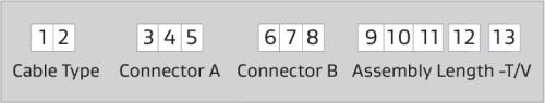
GORE Microwave RF Assemblies for general purpose are identified by a 13-character part number that designates the cable type, connector types, assembly length and T/V identifier for thermal vacuum chamber use.
Positions 1–2: Two-character code representing each cable type (e.g., 4L, 89, 2Z, 55, etc.).
Positions 3–5: Connector A that attaches to the left side of the cable assembly.
Positions 6–8: Connector B that attaches to the right side of the cable assembly
Positions 9–12: The assembly length is expressed in inches to the nearest tenth, including zeroes to fill positions if the length is less than three digits. For example, the length of a 24-in assembly is specified as 0240.
Position 13: Identifier T/V included only for an assembly prepared for thermal vacuum chamber use.
Example part numbers of our cable types include the following:
4LS01S010120
4LS01S010120-TV
890CQ0CQ0600
890CQ0CQ0600-T/V
G5D02D020240
G5D02D020240-TV
2Z0AK0AK0360
2Z0AK0AK0360-TV
G3R01R010120
G3R01R010120-TV
8WQ01Q010480
8WQ01Q010480-TV
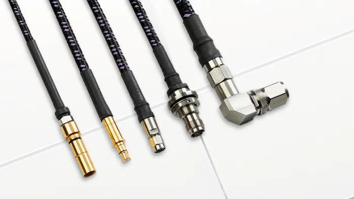
Connector Options
For all of our cable types, we offer a variety of standard connector options specifically designed to optimize the performance of each assembly, like SMA, SMP, TNCA, 2.92 mm and more.
Featured Content


Explore More
FOR INDUSTRIAL USE ONLY
Not for use in food, drug, cosmetic or medical device manufacturing, processing, or packaging operations.
Prefer to Call?
Have questions or unique requirements?
Our experts are here to guide you.