


Overview
Cables can be an essential component, even a lifeline, to electronic systems. If a cable goes down, the entire system can fail.
With four critical factors impacting their performance — mechanical, electrical, environmental and application-specific — manufacturers have to make sure cables can survive severe conditions and perform reliably over the system's lifespan. Whether they’re used in systems operating on land, underground, in the ocean, air or space, cables must be built to last.
Gore's cables and cable assemblies in durable, compact and flexible designs help to ensure the safety and success of every flight, mission, exploration, extraction, and production.
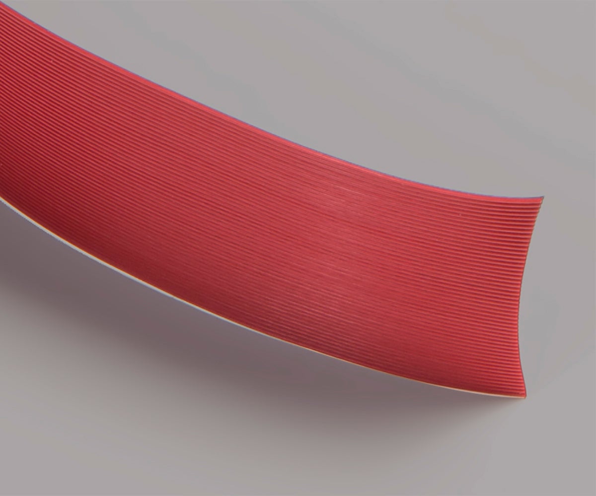
As applications have evolved, so have our engineering capabilities. In 1958, Gore began prototyping designs of fluorocarbon-insulated wires and ribbon cables for use in space vehicles, ground control equipment, and defense aircraft. Today, we combine our deep expertise in polymer materials technology with our extensive knowledge of signal integrity to provide high-performance solutions for commercial airliners, oil well drilling equipment, semiconductors and more.
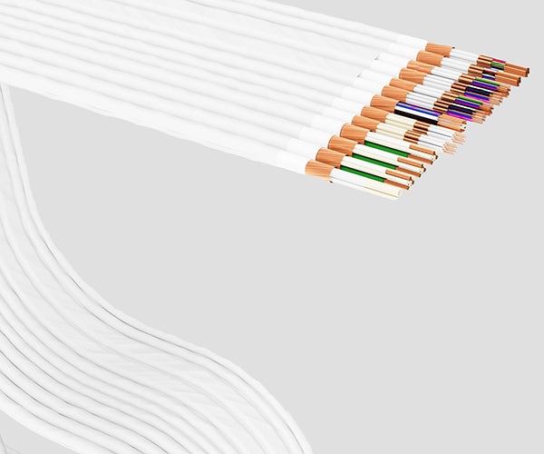
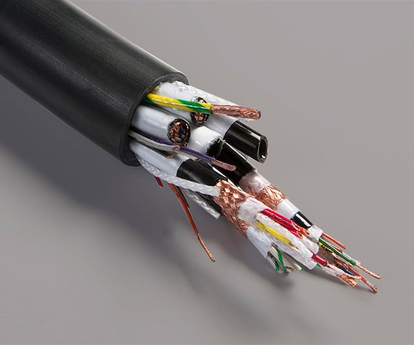
In even the toughest environments, our cables stay strong. That’s because we engineer them to have optimal characteristics like small size, low weight and outstanding strength.
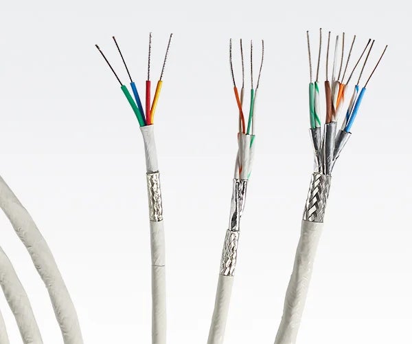
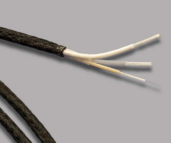
When designing a cable system, manufacturers can choose from a variety of materials, including:
- expanded polytetrafluoroethylene (ePTFE)
- polyurethane
- polyethylene
- polyimide
- fluoropolymers
While each material has its benefits, it can falter in certain applications. As an example, polyimide can withstand a wide range of temperatures, but it doesn’t perform well in environments where water is present. The wrong material makeup can have catastrophic consequences.
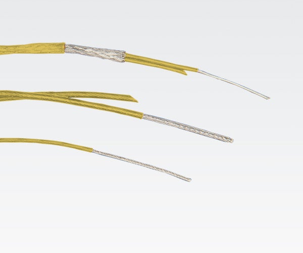
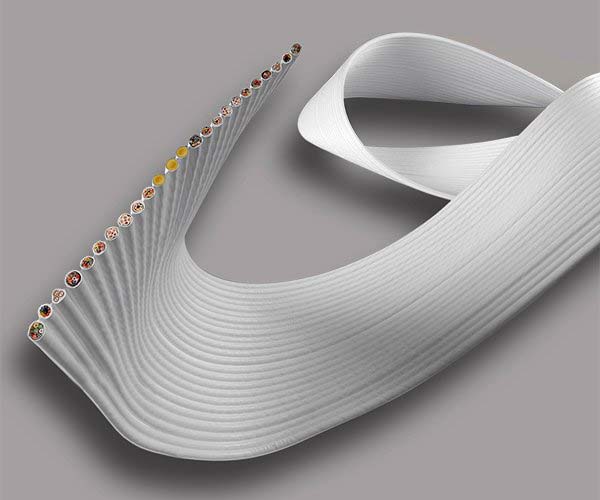
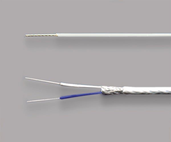
What sets Gore’s products apart is our proprietary technologies. We engineer fluoropolymers to withstand many environmental and mechanical challenges — maximizing benefits while eliminating issues and risks. For instance, if abrasion or cut-through is a risk, we can construct fluoropolymers to have a tensile strength 50 times greater than standard PTFE. For applications operating in extreme temperatures, we can manufacture fluoropolymers to withstand wide ranges from -55°C up to 300°C. If saving weight and maximizing space are issues, we can fabricate fluoropolymers to be thinner, making our products significantly smaller and lighter.
Most important: We can enhance these attributes while maintaining the other favorable properties of PTFE like low coefficient of friction, chemical resistance and low outgassing.
The result is reliability, but we go beyond that after manufacturing. At our laboratories, we reproduce extreme conditions in the highest degrees of physical stress and model end-user environments. We do this to ensure our products meet customers’ expectations and perform flawlessly for the life of the intended application — because system success depends on it.
Aerospace
We offer an extensive collection of high-performance wires, high-speed data cables, microwave/RF assemblies and protective cable jackets for many applications from the cockpit to the tail. They ensure power is distributed, signals are sent, and data is transmitted quickly with low loss for the duration of your system. Our rugged solutions save weight, solve many routing and protection challenges, deliver complete reliability in critical electronics and IFEC systems, remain in service longer and require less maintenance.
Defense Aircraft
Our solutions meet stricter military requirements for more durability that OEM system suppliers want and need while supporting the latest open-source architectures, standardized protocols and future aircraft electrification needs. They’re proven to deliver higher levels of protection and performance on modern avionics, ensuring mission-critical success. Solutions like GORE® Ethernet Cables, GORE® Fiber Optic Cables and GORE-FLIGHT® Microwave Assemblies continue to win industry awards for product and system-level innovations.
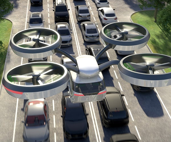
ADVANCED AIR MOBILITY
For autonomous, sustainable air transport, we’re leading the way with future-forward solutions that are made for urban air mobility and future aerial combat. Our small, lightweight wire and cabling products are a natural fit for eco-friendly aircraft with a low-carbon footprint. They offer unfailing high power, faster data speeds and higher antenna frequencies in vertical take-off and landing (VTOL) and electric VTOL aircraft, drones and future combat fighters transporting people and cargo. Products like GORE® Microwave/RF Assemblies are ideal in general purpose applications requiring little to no maintenance.
Civil Aircraft
Our products support current and next-generation system architectures as well as future onboard electrification needs. They continuously stream loads of data and video at high speeds, support high-resolution cockpit and cabin displays, quickly charge portable devices and ensure constant connectivity throughout the flight. Products like the 1.8 mm Simplex version of GORE® Fiber Optic Cables is proven to meet new, more stringent requirements for added durability.


Space
NewSpace
We’ve leveraged our materials expertise with proven spaceflight program heritage to offer reliable, affordable solutions that can be delivered quickly to meet demanding program schedules. They’re proven to send unfailing power, signals and data over frequent launch cycles and short missions that help connect us globally and monitor the earth. Small, low-mass GORE® Space Cables and Assemblies are appropriately tested, qualified and low risk for smaller launch vehicles and mini satellites operating in low and medium earth orbits.
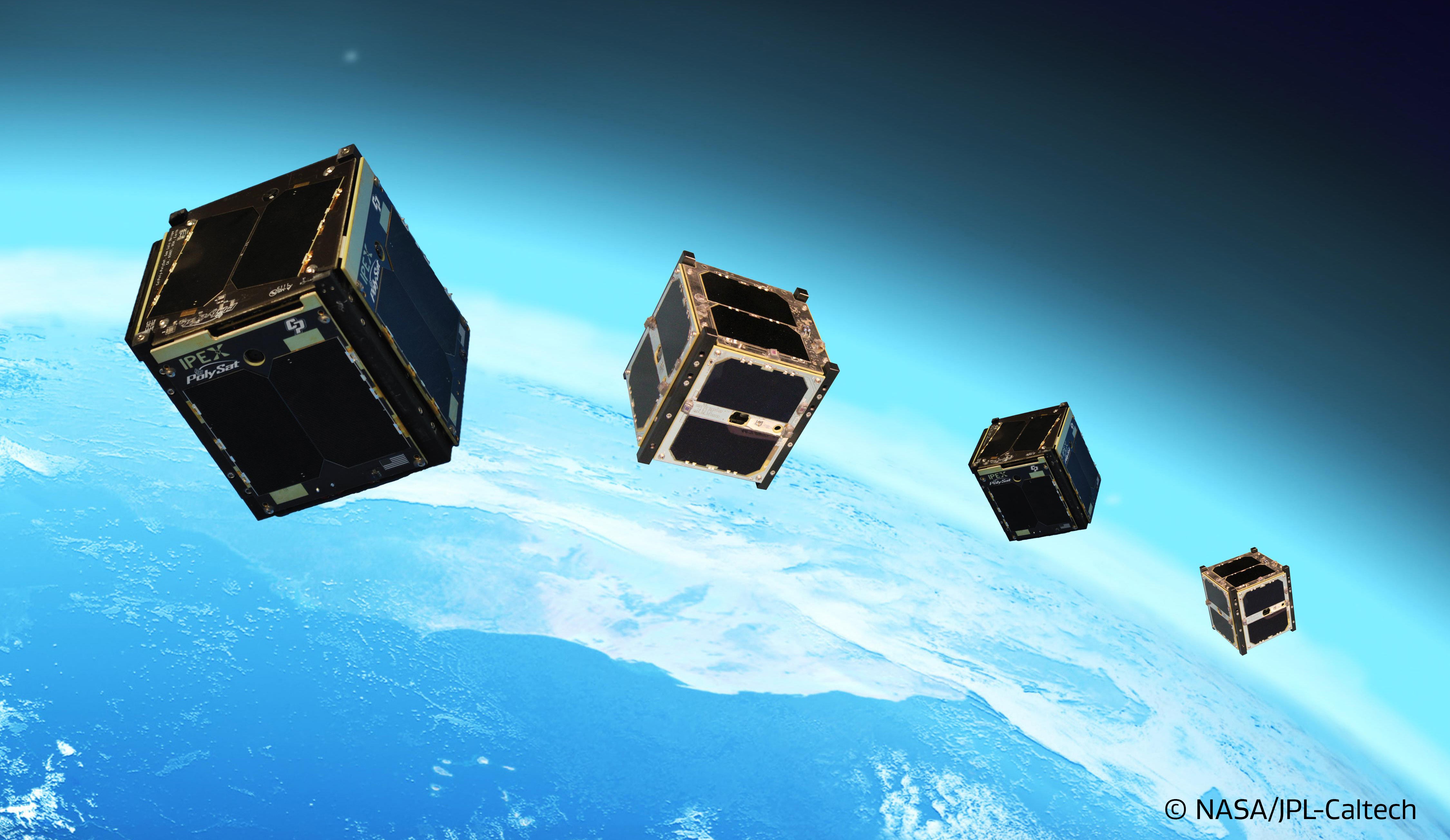
Whether supplying power, transmitting signals or sending earth images, Gore’s products are engineered to perform without failure despite the environment. By combining our innovative materials and dielectric expertise, our durable solutions withstand a broad spectrum of challenges common during spaceflight, exploration and monitoring. Conditions like extreme temperatures from -200°C to +200°C, repeated shock and vibration, radiation exposure and hazardous chemicals won’t degrade the performance of our products, no matter the mission duration.
Traditional Space
Major organizations like ESA and NASA have trusted our products in critical systems operating in earth's orbit and deep space. They’re proven to boost power and transmit signals with low loss at high speeds and high frequencies consistently, reliably and safely. Low-mass solutions like GORE® Spaceflight Microwave/RF Assemblies and GORE® Space Cables have ensured constant communications from space to earth during many iconic spaceflight programs over the decades.

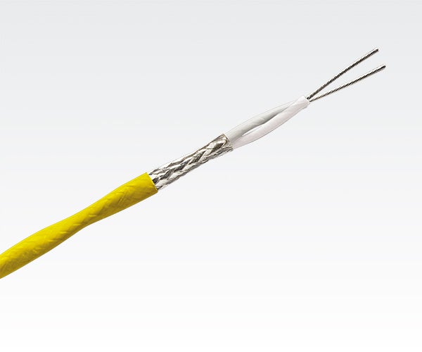
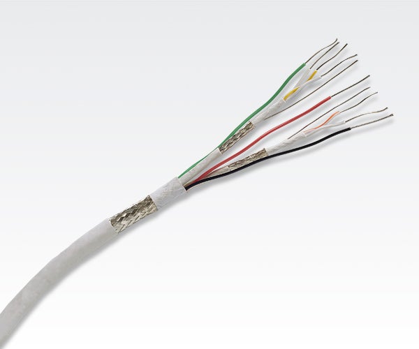
Land Systems
It's the cable's job to supply power to electronics and send real-time Intel to our soldiers no matter the conditions on land. Cable durability is a key factor, and Gore manufactures a broad selection of small-scale solutions in fiber and copper that provide armored protection while delivering stable electrical performance. Extreme heat up to 200°C, arctic temperatures down to -65°C, muddy conditions, and complex routing are examples that won't penetrate, scrape or cut through our uniquely engineered materials.
This unmatched level of durability coupled with fast, long-lasting power and signal transmission is why the military has continued to trust our products to maintain secure communications on the battlefield.
Land Systems
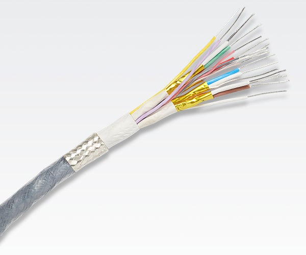
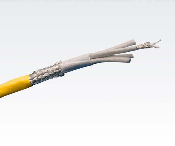
Semiconductor & Microelectronics
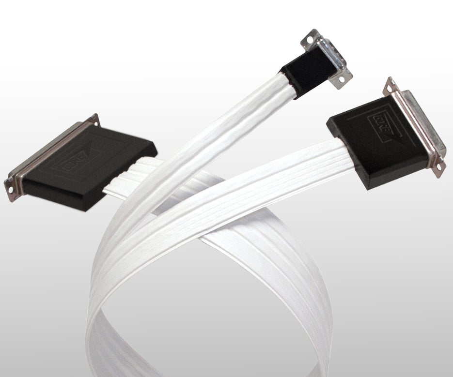
Gore works closely with equipment manufacturers to deliver advanced solutions with the cleanliness and durability that enable current and next-generation systems to run at even higher speeds and output with higher precision and less downtime. Our clean cabling solutions ensure reliable signal transmission in high-vacuum and cleanroom environments.
Products like GORE® High Flex Cables and Assemblies meet Cleanliness Grades 2 & 4 for extreme lithography ultraviolet (EUV) and deep ultraviolet (DUV) applications. For semiconductor production equipment, GORE® Trackless High Flex Cables are certified to ISO Class 1 motion control systems and electrostatic discharge (ESD) environments. Finally, our microwave/RF assemblies deliver accurate, repeatable measurements with design flexibility in semiconductor and chip test systems.
Semiconductor & Microelectronics
Test & Measurement
Electronic systems, like those aboard aircraft and in 5G communications, must be thoroughly tested and measured to ensure their performance in use. Constantly moving, flexing and mating test assemblies can compromise the equipment’s signal quality and measurement precision. You can't trust the cable's performance if you can't trust the test results.
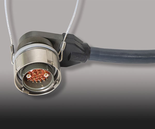
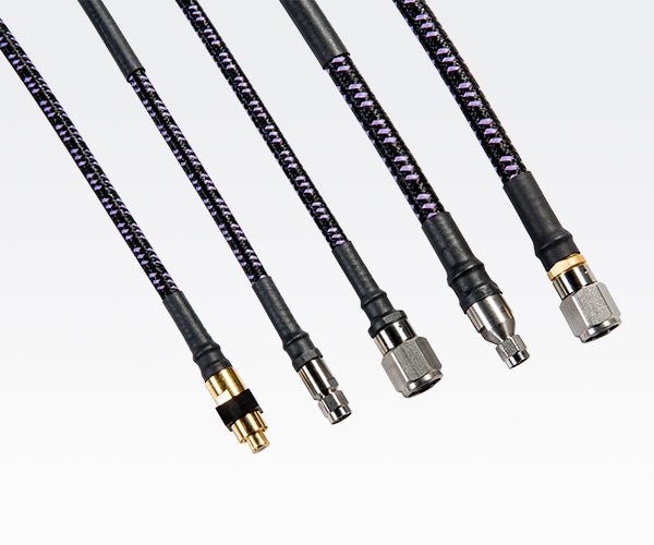
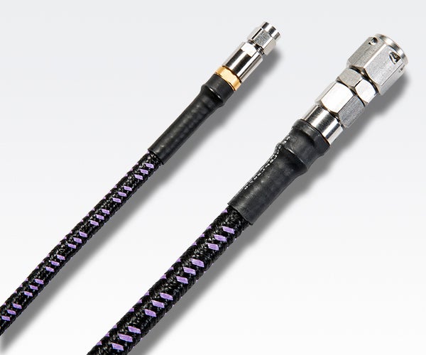
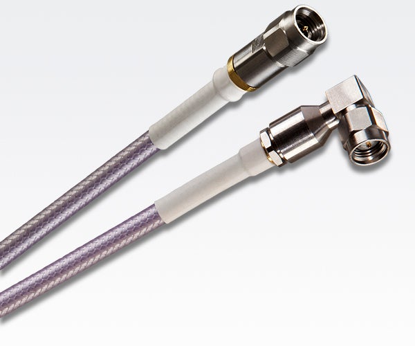
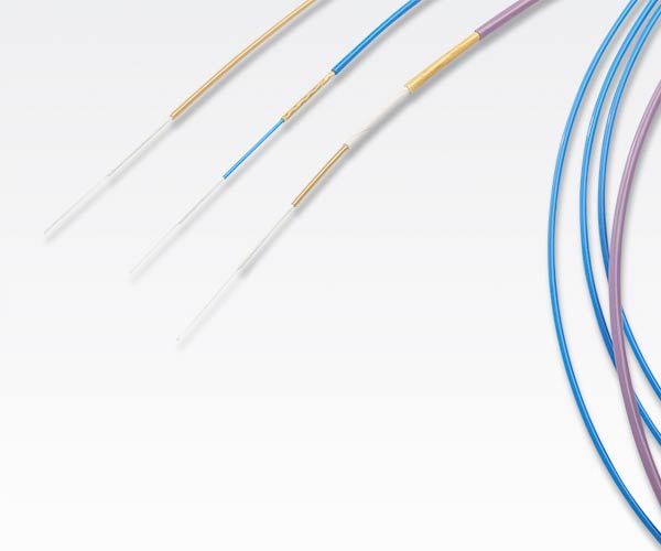
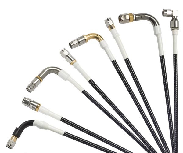
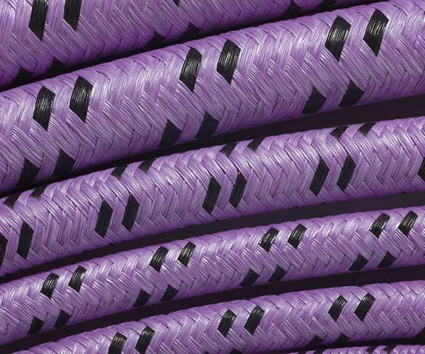
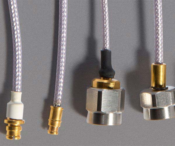
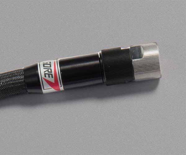
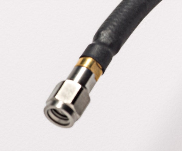
Gore offers a full range of high-flex microwave/RF test assemblies that deliver precise and repeatable measurements with enhanced phase and amplitude stability from DC to 110 GHz. Our rugged assemblies with robust connector options are proven to perform reliably now and over time for less equipment downtime and lower costs to run tests in laboratory, production and field environments.
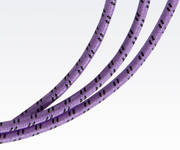
Known as the purple cable, GORE® PHASEFLEX® Microwave/RF Test Assemblies have been awarded by the military and aerospace community for their durability, reliability and precision testing in complex settings. With our assemblies connected to your test and measurement equipment, you can always trust the results!

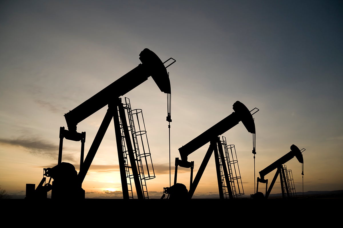
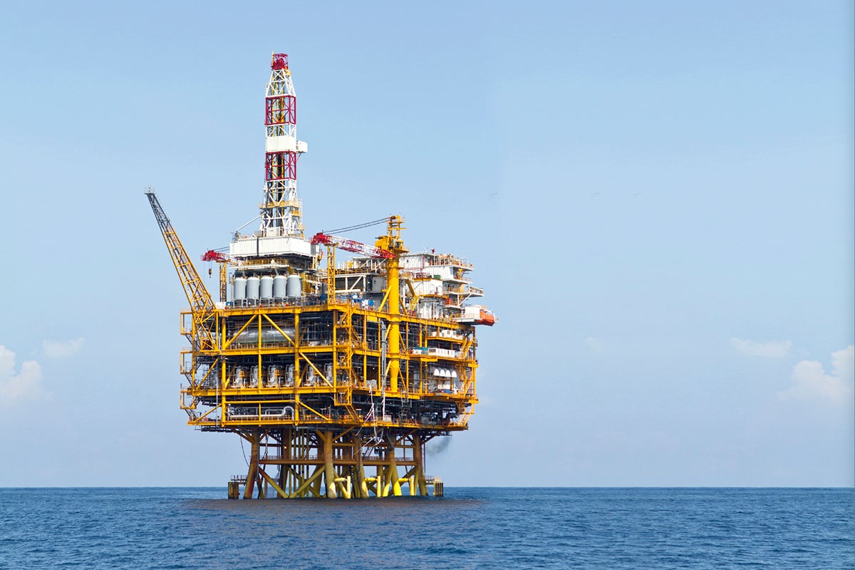
Harsh Environments & Industrial Automation
From oil and gas downhole drilling, processing natural resources and marine geophysical exploration to cleanrooms, Gore’s products are built specifically to withstand extreme environments while meeting strict industry requirements and regulations. Whatever the environment — high pressure, high temperature, continuous flexing, deep water — we deliver durable solutions that function accurately, reliably and efficiently over the system’s lifecycle. Our products help manufacturers optimize their processes and improve tool/equipment reliability for fewer failures and costly delays.
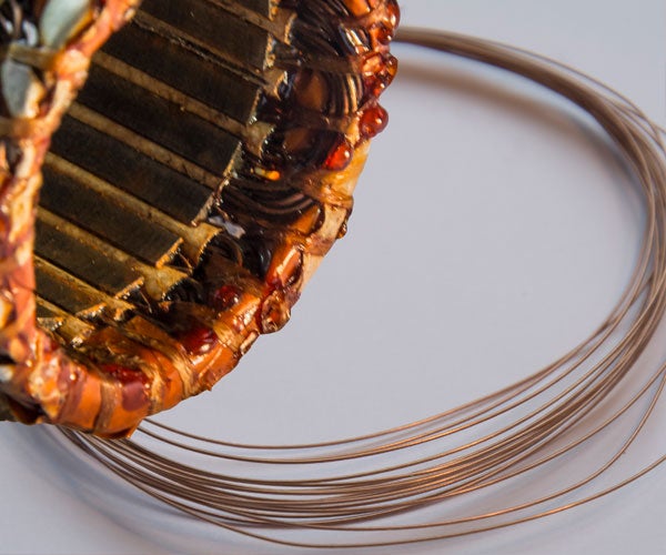
We continue to combine industry expertise with advanced technical capability to develop leading-edge solutions. We're proud to be recognized in the industry for our outstanding use of fluoropolymers in products like GORE® High Temperature Capacitors for oil and gas power electronics.
Harsh Environments & Industrial Automation
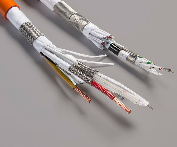
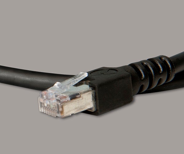
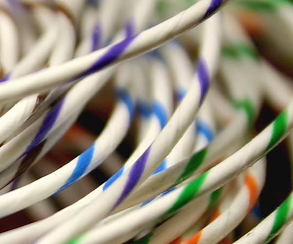
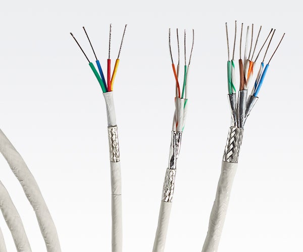
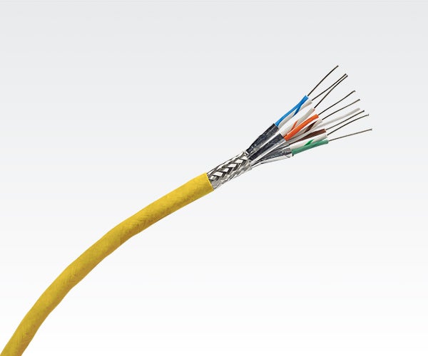
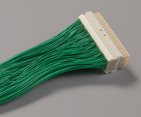
Computing & Networking
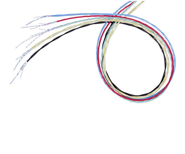
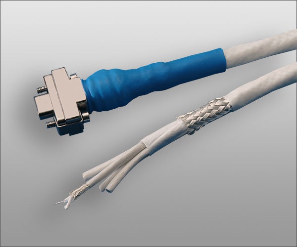
Gore meets the industry’s ever-growing need for customized cables that provide high data rate performance in computing, networking and laboratory environments. With a small yet durable construction, our high-speed twinax cables deliver exceptional electrical and mechanical performance, including applications that operate in extreme temperatures.
Follow Cables & Cable Assemblies