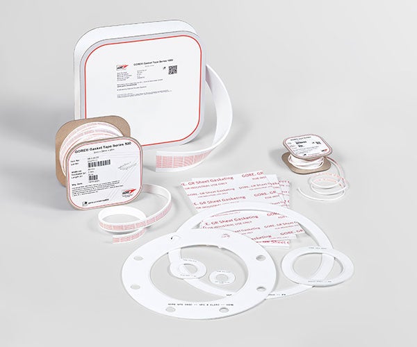
GORE® GR Sheet Gasketing
Exceptionally resistant to creep, cold flow and aggressive media, this 100% expanded PTFE gasket sheet reliably seals steel piping and equipment.
Contact Us
United States
+1 800 654 4229
Australia
+61 2 9473 6800
Brazil
+55 11 5502 7800
China
+8621 5172 8299
France
+33 1 56 95 65 65
Germany
+49 89 4612 2215
Hong Kong
+852 2622 9622
India
+91 22 67687000
Italy
+39 045 6 20 92 50
Japan
+81 3 6746 2600
Korea
+82 2 393 3411
Netherlands
+31 13 507 47 00
Poland
+48 22 6 45 15 37
Scandinavia
+46 31 706 78 00
Singapore
+65 6733 2882
South Africa
+27 71 467 7710
Spain
+34 93 4 80 69 00
United Arab Emirates
+971 2 5089444
United Kingdom
+44 1506 46 01 23
Resource Library
Gasket Product Selection Guide
Product Selection Guides, 271.24 KB
Guide to verify that the application meets GORE® Gasketing qualifications, and to narrow the selection of products.
All Resources For GORE® GR Sheet Gasketing
- Installation Guides (5)
- Product Selection Guides (2)
- Industry Articles (2)
- Data Sheets (2)
- Videos (2)
- Brochures (1)
- Safety Information (1)
- Certifications (3)
Overview
GORE GR Sheet Gasketing is designed to outperform both conventional (filled and skived) PTFE and other ePTFE gasketing in steel piping and equipment.
GORE GR Sheet Gasketing has the chemical resistance of conventional PTFE sheet gasketing without the creep and cold flow commonly associated with that material. GORE GR Sheet Gasketing is stronger and more dimensionally stable than other ePTFE gaskets. It is highly conformable to rough or irregular sealing surfaces, and compresses into an extremely tough gasket that creates a tight, long-lasting seal.
Whether you use a single sheet to make one very large (1.5 m x 1.5 m) gasket or multiple smaller pipe flange gaskets, GORE GR Sheet Gasketing is a versatile, single-solution material for both standard and custom gasketing shapes and sizes.
Applications
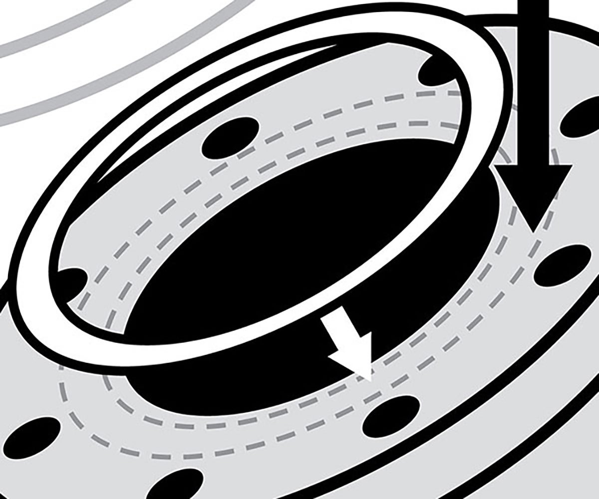
GORE GR Sheet Gasketing is a tough, dimensionally-stable and chemical-resistant gasket sheet for sealing steel pipe and equipment flanges in a wide range of applications and process conditions. It reliably seals flanges with rough surfaces, and is ideal for flanges that require complex gasketing shapes or larger gasketing sizes.
Processes utilizing highly-aggressive media, as in:
- Chemical processing
- Pulp and paper manufacturing
- Mining and minerals
- Semiconductor manufacturing
- Power generation
Large, complex or non-standard steel equipment flanges in:
- Columns
- Reactors
- Turbines
- Heat exchangers
- Tanks
- Pipe flanges
APPLICATIONS FOR GORE GR SHEET GASKETING
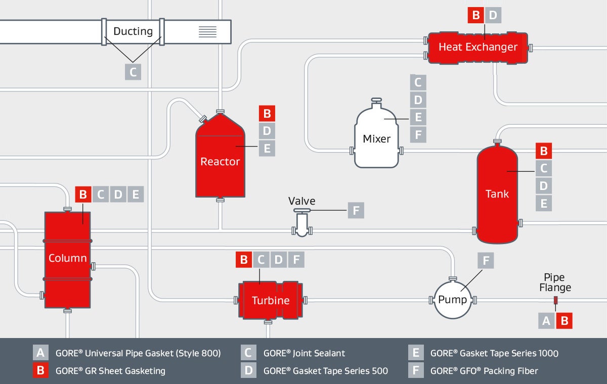
GORE® GR Sheet Gasketing performs durably across a range of challenging applications, reliably sealing steel flanges that demand a chemical-resistant gasket material or a high-temperature gasket sheet.
Performance Benefits
Whether your application requires long-term reliable sealing, a high-temperature gasket or chemical-resistant gasketing, GORE GR Sheet Gasketing offers all of that — as well as a number of additional performance advantages.
WHY CAN GORE DELIVER SUPERIOR SHEET GASKET PERFORMANCE PROPERTIES?
Proprietary, patented technology
Gore’s 100% expanded PTFE sheet material is specially engineered for high performance. Our patented manufacturing technology creates an ePTFE sheet with the highest degree of expansion available. Other ePTFE material has many un-expanded nodes. The increased expansion of GORE GR Sheet Gasketing gives it superior tensile strength and dimensional stability, creating significant performance advantages in demanding applications.
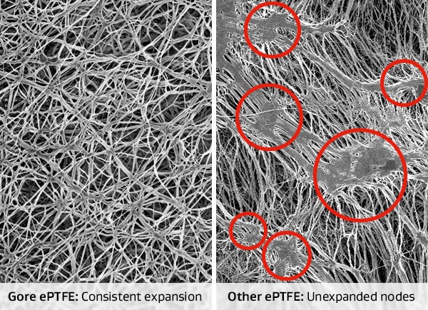
Gore’s ePTFE is more highly-expanded and consistent than other ePTFE, for superior performance in demanding applications.
Superior resistance to creep and cold flow
GORE GR Sheet Gasketing has greater tensile strength, so it retains greater dimensional stability in-use — in both size and width — than any other PTFE-based or ePTFE flange gasket sheets.
- Because its creep-resistance is better than that of any other PTFE-based gasket, GORE GR Sheet Gasketing maintains a greater percentage of bolt load in operation, providing a more reliable solution for making flange connections, especially in thermal cycling and high heat conditions.
- The width of GORE GR Sheet Gasketing also remains more dimensionally stable, avoiding gasket intrusion into the pipe bore which can negatively affect process performance.
- Along with providing a larger window for blowout safety, the dimensionally-stable seal can also increase process uptime and reduce maintenance costs associated with gasket re-torque and replacement.
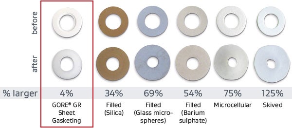
Tests show that, even in high heat, GR Sheet Gasketing is more dimensionally stable than other PTFE or ePTFE gasketing. (Tested at 34.5 MPa (5000 psi) load, 230 °C (446 °F) for 15 minutes.)
Exceptionally reliable sealing performance
Crush-resistance tests show GORE GR Sheet Gasketing excels at withstanding the extreme conditions of industrial flange sealing. It delivers a wider safety margin of seal reliability, both at installation and in operation at elevated temperatures.
Chemically-inert GORE GR Sheet Gasketing seals durably, whether in strong alkali-, acid- or solvent-based process systems. It resists all media (pH 0-14) except for molten/dissolved alkali metals and elemental fluorine.
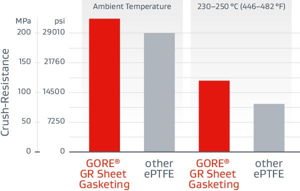
GORE GR Sheet Gasketing creates a durable, reliable seal that offers a wider safety margin than other ePTFE at installation and under harsh operating conditions.
Greater consistency, for fewer problems
The consistency and precision of Gore manufacturing processes give GORE GR Sheet Gasketing a much more uniform distribution of mass than other ePTFE sheets. This promotes a more uniform and reliable seal.
Unlike skived or filled PTFE, GORE GR Sheet Gasketing readily conforms to common flange imperfections. Gore’s flange gasket sheet can eliminate the need for flange resurfacing, expand the window of applicability and create a highly reliable initial seal, so start-ups can be more trouble free.
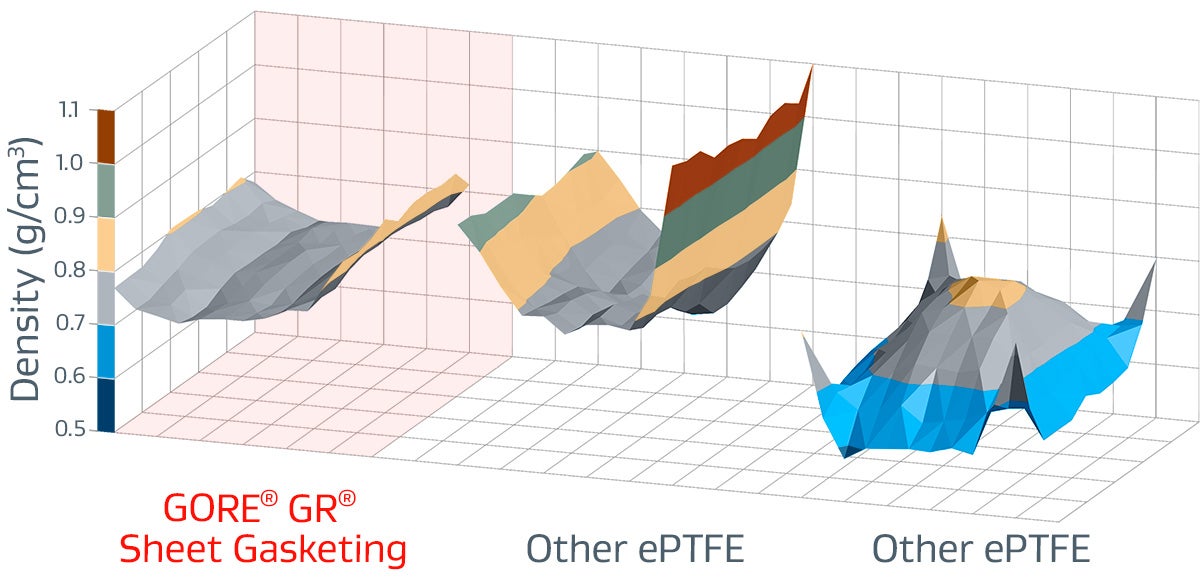
Gore manufactures a more consistently dense and conformable product, so GORE GR Sheet Gasketing can seal rough or damaged flanges more reliably.
Technical Specifications
Test Data
Test Results
| Thickness | Compressibility (average of 3 tests) |
Recovery (average of 3 tests) |
|
ASTM F36-95 Procedure L
|
1.5 mm (1/16") |
56% | 8% |
Test Method
The ASTM F36 test method covers determination of the short-time compressibility and recovery at room temperature of sheet-gasket materials. It is not intended as a test for compressibility under prolonged stress application, generally referred to as "creep."
Source: ASTM International. Standard Test Method for Compressibility and Recovery of Gasket Materials - Designation: F36–99 (Reapproved 2009)
Test Results
| Thickness | Relaxation (average of 3 tests) |
|
ASTM F38-95 Method B
|
0.8 mm (0.030") | 23% |
Test Method
ASTM F38 provides a means of measuring the amount of creep relaxation of a gasket material at a predetermined time after a compressive stress has been applied. This test method is designed to compare related materials under controlled conditions and their ability to maintain a given compressive stress as a function of time.
Source: ASTM International. Standard Test Methods for Creep Relaxation of a Gasket Material - Designation: ASTM F38-00 (2014)
Test Results
| Thickness | Leak rate | |
ASTM F37-95 Test Method B
|
1.5 mm (1/16") | 0.3 ml/h |
Test Method
ASTM F37 provides a means of evaluating the sealing properties of sheet and solid form-in-place gasket materials at room temperature. This test method is designed to compare gasket materials under controlled conditions and to provide a precise measure of leakage rate.
Source: ASTM International. Standard Test Methods for Sealability of Gasket Materials - Designation: ASTM F37-06 (2013)
Test Results
| Gasket Thickness | % Relaxation (Average of 3 Tests) | Helium Leak Rate before aging (mg/s) | Helium Leak Rate after aging (mg/s) | |
| ARLA1 |
1/16" |
31 | 1.04E-04 | 1.42E-05 |
| 1/8" | 43 | 1.04E-03 | <1.0E-7 |
1 Compressive stress 34.5 MPa (5000 psi); 4 days at 315 °C (600 °F); 55.2 bar (800 psig) Helium
Test Method Overview
This test method is currently being proposed as a new ASTM test method by the Committee F03 on Gaskets. ARLA determines the long term (aged) relaxation, leakage, weight loss and adhesion performance of gasket materials for pressurized bolted flanged connections. A mechanical integrity check of the material is also done. The method applies mainly to circular gasket products typically used in process or power plant pressure vessels and piping.
Source: ASTM International. New Test Method for AGED RELAXATION LEAKAGE ADHESION PERFORMANCE of Gaskets - Designation: ASTM WK26065
General Test Method
- Place the gasket in the ARLA fixture
- Measure the distance between platens
- Load the gasket to initial compressive stress
- Measure the stud length
- Measure the distance between platens
- Measure the leak rate (using a Helium Mass Spectrometer) using helium gas at 800 psig
- Age by placing the loaded fixture in a non-circulating air oven
- Remove the fixture from the oven and cool to room temperature
- Measure the stud length
- Measure the distance between platens
Test Results
| Thickness | Exposure Temperature | Initial Gasket Stress | Test Step 1 | Test Step 2 | |
| VDI 2200 (06-2007) DN40 / PN40 Steel |
3.0 mm (1/8") |
230°C (446°F) |
30 MPa (4350 psi) |
Yes, 60 bar (870 psi) |
Yes, 50 bar (725 psi) |
Test Method
"The aim of the VDI guideline is to analyze and organize the applicable seal connection conditions based on the technical standard. Furthermore to complete the conditions, including latest research results, and advise the user in selection, interpretation, design, and assembling of flange joints in particular consideration of the gaskets."(1) "The here described blowout safety test of seals in sealing systems with even flanges corresponds with the current state of test engineering [...] a seal itself cannot accomplish blowout safety. It always depends on the entire system of the flange joint."
General Test Procedure
- Installation of seal with installation surface pressure in four steps (25 %, 50 %, 75 % and 100 % of bolt force through crosswise tightening). Installation surface pressure and seal thickness are to be indicated in the test record. The lift-off force, caused by the nominal pressure, referring to the middle seal diameter, shall additionally be considered in all testing steps.
- Retightening to installation surface pressure after 5 minutes.
- Flange heating to temperature with 2 K/min in recirculation furnace or using inside heated cartridges.
- Maintenance of thermal storage temperature for minimum 48 hours.
- Cooling down of the flange to ambient temperature.
- Measurement of the remaining surface pressure.
Test Step 1
The blowout safety test is performed with nitrogen up to the 1.5-fold of the nominal pressure. Tests with higher pressures are allowed, if required. The internal pressure is to be increased stepwise, in steps of 5 bar to the above mentioned pressure. The holding period per pressure stage amounts to a minimum of 2 min.
As "blowout" is defined, if, within 5 s, a pressure decay of Δp ≥ 1 bar· (V0 = test room volume) is exceeded. The achieved internal pressure is to be indicated in the test record. If blowout did not occur until the maximum test pressure, the test is to be continued according to test step 2.
Test Step 2
The internal pressure is discharged and the surface pressure is reduced to 5 N/mm2 with regard to lifting force caused by the internal pressure. Variations of the surface pressure are to be stated in the testing report."(2)
(1) Source: Verein Deutscher Ingenieure e. V.: VDI 2200: Tight flange connections - Selection, calculation, design and assembly of bolted flange connections, June 2007, page 4
(2) Source: ibidem, page 64
Test Results
| Gasket Thickness | Blowout Temperature | Blowout Stress | Blowout Pressure | Trial Gasket Temperature Tgr | |
| HOBT with Cycling Draft 71 |
3.0 mm (1/8") |
392.2 °C (738 °F) |
8.8 MPa (1271 psi) |
30 bar (435 psig) |
Actual: 339 °C (635 °F) Limited to: 315 °C (600 °F) |
1 NPS 3 Class 150 Slip-on Flange at 34.5 +/- 1.7 MPa (5000 +/- 250 psi), 30 bar (435 psig) Helium
Test Method
This test method is currently being proposed as a new ASTM test method by the Committee F03 on Gaskets. This test method provides a means to determine realistic temperature limits for polytetrafluoroethylene (PTFE) based sheet or sheet-like gaskets to assist in avoiding catastrophic failure or blowout. This test method focuses on flanged joints common in the chemical process industry for moderate temperature ASME B16.5 Class 150 and Class 300 services.
Source: ASTM International. New Test Method for Hot Blowout and Thermal Cycling Performance for Polytetrafluoroethylene (PTFE) Sheet or Sheet-Like Gaskets - Designation: ASTM WK26064
General Test Procedure (Draft 7)
- A gasket is loaded in a Hot Blow Out Test Rig, which is comprised of NPS 3 Class 150 or Class 300 raised face flanges. Using a torque wrench and best installation practices, the specified compressive stress is applied to the gasket.
- A waiting period for gasket creep and relaxation of 30 minutes is observed before the gasket is reloaded to the specified gasket stress.
- Another 30 minutes waiting period is observed before the rig is pressurized with helium gas.
- For HOBT without thermal cycles, once the pressure is applied, the temperature is increased up to 648.9°C (1200°F) maximum at a 16.1°C (3°F) per minute rate until blow-out or maximum temperature of the rig is reached.
- For HOBT with thermal cycles, once the pressure is applied, the temperature is increased at 16.1°C (3°F) per minute rate. The fixture is then cooled to room temperature. This cycle is repeated two more times for a total of three thermal cycles per test.
The procedure consists of three tests:
Test 1: HOBT without thermal cycles.
Test 2: HOBT with 3 thermal cycles using temperature estimation from Test 1.
Test 3: HOBT with 3 thermal cycles using temperature estimation from Test 2.
Test Results
| ROTT Draft 9 | GORE GR Sheet Gasketing | |
|---|---|---|
| Soft Gasket Test | Gasket Thickness: 1/16" | Gasket Thickness: 1/8" |
| Gb (psi) | 685 | 770 |
| a | 0.271 | 0.274 |
| Gs (psi) | 6.19E-02 | 9.38E-07 |
| Tpmin | 1416 | 1962 |
| Tpmax | 27706 | 16424 |
| S100 (psi) | 2391 | 2716 |
| S1000 (psi) | 4466 | 5099 |
| S10000 (psi) | 8343 | 9573 |
| Maximum Allowable Gasket Stress (psi) | Greater than 40030 (Equipment Max) | Greater than 40030 (Equipment Max) |
Test Method
This test method is currently being proposed as a new recommended practice for Gasket Constants for Bolted Joint Design by the Committee F03 on Gaskets. This practice determines room temperature gasket tightness design constants for pressurized bolted flanged connections such as those designed in accordance with The ASME Boiler & Pressure Vessel Code. It applies mainly to all types of circular gasket products and facings typically used in process or power plant pressure vessels, heat exchangers and piping including solid metal, jacketed, spiral wound and sheet type gaskets. As an option, the maximum assembly stress for those gaskets is also determined by this procedure.
Source: ASTM International. New Recommended Practice for GASKET CONSTANTS FOR BOLTED JOINT DESIGN - Designation: ASTM WK10193
Definitions of Test Parameters
| Gb | The gasket stress at Tp = 1 when loading the gasket. It indicates the initial gasket stress required to seat the gasket with tightness. |
|---|---|
| "a" | The slope obtained by linear regression. It indicates the capacity of the gasket to ensure tightness. |
| Gs | The gasket stress at Tp = 1 when unloading the gasket. It indicates the capacity of the gasket to maintain tightness when pressure is applied, as well as the gasket's sensitivity to unloading. |
| Tp | The Tightness Parameter is dimensionless. A value of 1 corresponds to a Helium leak rate of 1 mg/s under atmospheric pressure for a gasket with an outside diameter of 150 mm. Note: the greater the Tp, the greater the gasket tightness. |
| Tpmax | The maximum tightness obtained when loading the gasket. |
| Tpmin | The minimum tightness obtained when unloading the gasket. |
General Test Procedure for Soft Gaskets (Draft 9)
- A gasket is placed in a hydraulic flat platen test rig.
- A series of 3 loadings and unloading cycles is applied during which leak rate is measured at each stress level. Depending on the step, the system is pressurized to either 27.5 bar (399 psi) or 55 bar (798 psi) using helium gas. The holding time at each step is dependent on when a leak rate stabilizes, with a minimum hold time of 1 minute and a maximum hold time of 5 hours.
- The data collected is grouped into two Parts, Part A and Part B, and analyzed to generate the test parameters. Part A represents the initial seating performance of a gasket during initial flange tightening. Data from Part A is used to determine Gb, "a", and Tpmax. Part B simulates actual operating conditions. Data from Part B is used to determine Gs and Tpmin.
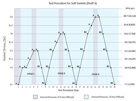
ROTT Test Procedure for Soft Gaskets
General Test Procedure for CRUSH (Draft 9)
- The gasket stress is restored to S1 level.
- Loading cycles, with gradually increasing compression stresses, are applied on the gasket during which leak rate is measured at each stress level. The system is pressurized to 27.5 bar (399 psi) using helium gas. The holding time shall not exceed 15 minutes at each stress level.
- The test is complete when the leak rate at a stress level exceeds the leak rate observed at S1 level or when the maximum load of the equipment is reached.
- Maximum Allowable Stress is the maximum stress level where S1 leak rates were maintained.
Gasket Design Factors
CERTIFICATES & APPLICATION INFORMATION
Resources

Data Sheet: GORE® GR Sheet Gasketing
Data Sheets, 112.8 KB
Installation Guide: GORE® GR Sheet Gasketing
Installation Guides
GORE® GR Sheet Gasketing conforms to the US FDA 21CFR and EU directive EC 1935/2004 requirements relating to food contact. Declaration of Compliance is available upon request.