GORE® Joint Sealant
Versatile and easy-to-install, this 100% ePTFE sealing cord is a cost-effective solution for large steel flanges in general-use applications.
Contact Us
United States
+1 800 654 4229
Australia
+61 2 9473 6800
Brazil
+55 11 5502 7800
China
+8621 5172 8299
France
+33 1 56 95 65 65
Germany
+49 89 4612 2215
Hong Kong
+852 2622 9622
India
+91 22 67687000
Italy
+39 045 6 20 92 50
Japan
+81 3 6746 2600
Korea
+82 2 393 3411
Netherlands
+31 13 507 47 00
Poland
+48 22 6 45 15 37
Scandinavia
+46 31 706 78 00
Singapore
+65 6733 2882
South Africa
+27 71 467 7710
Spain
+34 93 4 80 69 00
United Arab Emirates
+971 2 5089444
United Kingdom
+44 1506 46 01 23
Resource Library
Gasket Product Selection Guide
Product Selection Guides,
Guide to verify that the application meets GORE® Gasketing qualifications, and to narrow the selection of products.
All Resources For GORE® Joint Sealant
- Product Selection Guides (2)
- Industry Articles (1)
- Data Sheets (2)
- Videos (2)
- Installation Guides (2)
- Certifications (3)
- Brochures (1)
- Safety Information (1)
Overview
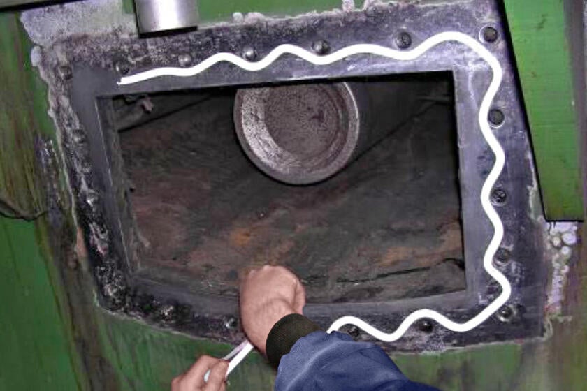
GORE Joint Sealant, the first form-in-place gasket material, was invented by Gore more than 50 years ago. Since then, this high-temp rope gasket material has proven successful in sealing steel flanges with large diameters, rectangular or irregular shapes, and rough or pitted surfaces.
When compressed, this soft, conformable cord forms a thin yet strong seal. This high-temp rope gasket material is also a chemical-resistant joint sealant that will withstand challenging process conditions and aggressive process media. It can also seal applications where available bolt loads are low, or in applications that demand a gas-tight sealant.
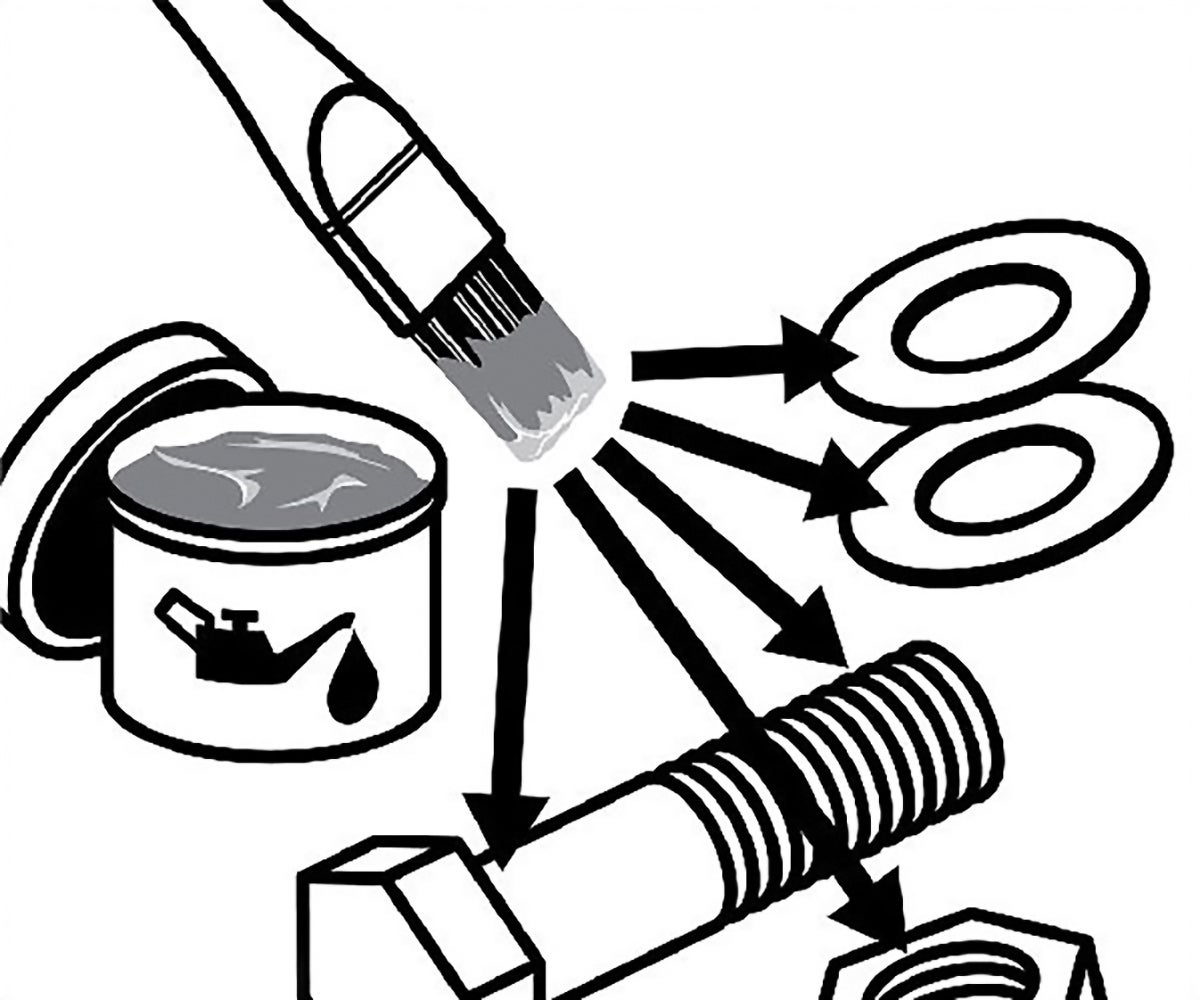
GORE Joint Sealant is a versatile general assembly sealant for many Maintenance, Repair and Operations (MRO) teams because it seals reliably — and because this form-in-place seal is easy and cost-effective to install. For most applications, just peel off the adhesive backing, apply to the surface, and overlap the ends. (For more complex applications, see our installation instructions.)
Of all the joint sealant types, this durable industrial sealant is surely one of the easiest and most versatile solutions for a wide variety of gasketing applications.
Applications
Processes using highly-aggressive media:
- Chemical processing
- Pulp and paper
- Mining and minerals
- Semiconductor manufacturing
- Power generation
Processes requiring an expanded PTFE joint sealant material:
- Those that demand a high-temperature joint sealant
- Those that employ highly-corrosive media
- Those that need a gas-tight sealant or vacuum gasket cord
Large and/or non-standard steel equipment flanges:
- Tank manways
- Handholes and manholes
- Ductwork
- Housing covers
APPLICATIONS FOR GORE JOINT SEALANT
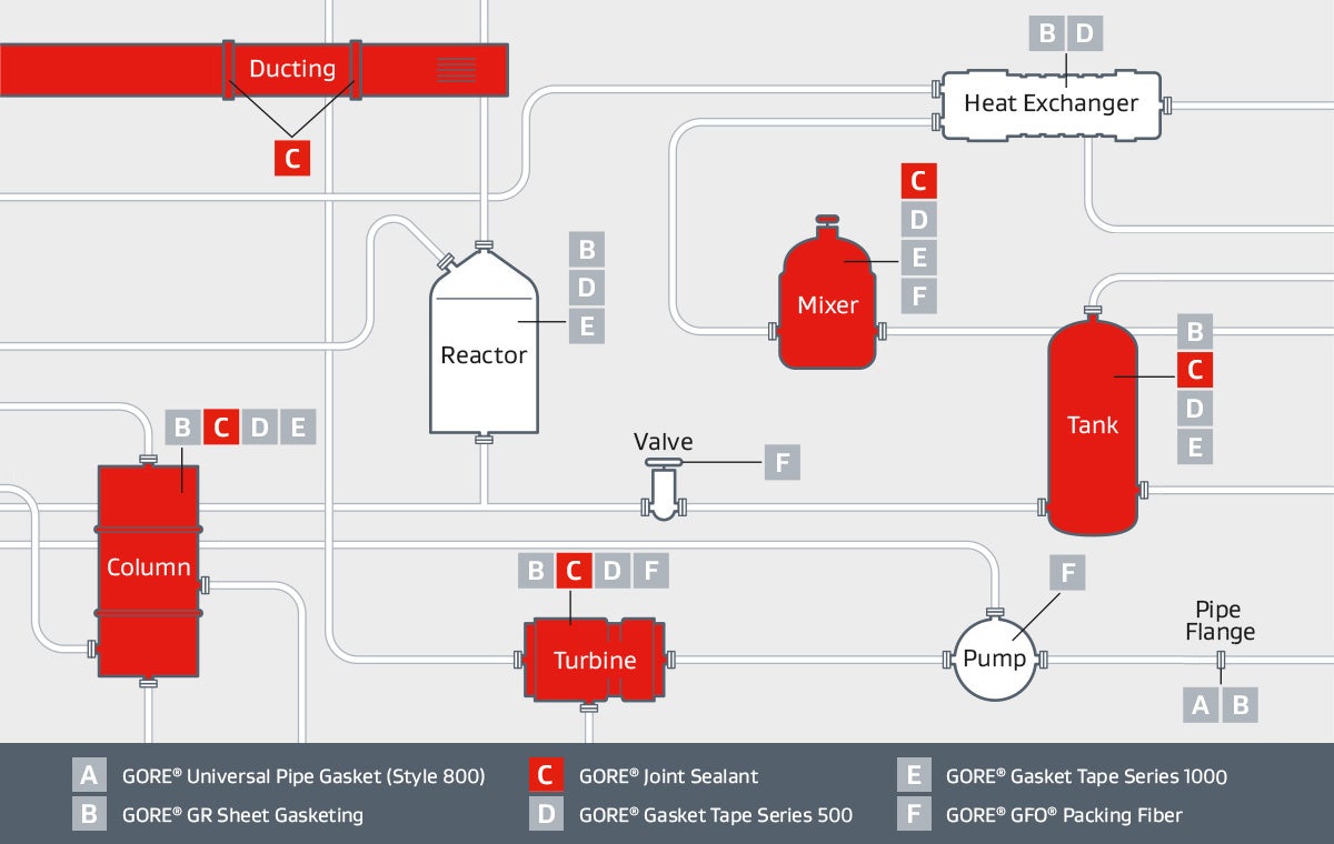
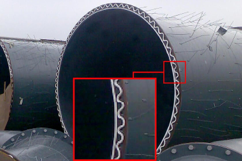
GORE® Joint Sealant creates form-in-place gaskets that reliably seal steel flanges in ducting, columns, turbines, mixers and tanks.
Performance Benefits
WHAT MAKES GORE JOINT SEALANT SO VERSATILE?
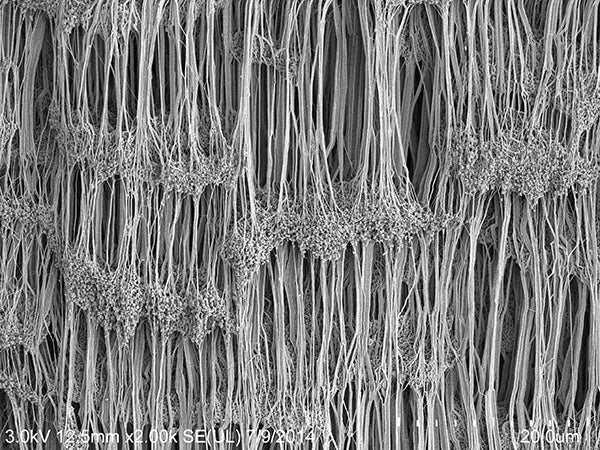
Gore’s expansion technology creates fibrils that enable GORE Joint Sealant to seal irregular flange surfaces more reliably.
Gore’s expanded polytetrafluoroethylene technology
GORE Joint Sealant is made of 100% monoaxially expanded PTFE (ePTFE), using Gore’s expansion technology to create a high degree of fibrillation.
High fibrillation is what improves the joint sealant material’s strength and seal performance, and creates the soft, conformable surface that readily fills minor flange irregularities.
GORE Joint Sealant is versatile enough for use in strong alkali-, acid- and solvent-based chemical process systems, as it is chemically resistant to all media (pH 0-14) except molten/dissolved alkali metals and elemental fluorine.
HANDLING AND INSTALLATION? SIMPLICITY ITSELF
GORE Joint Sealant is an easy, cost-effective solution for a wide variety of sealing and gasketing applications.
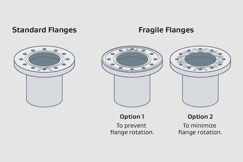
This rope gasket material can instantly be formed in place to fit any shape, regardless of flange size or complexity, or flange condition. It offers installation options for fragile flanges, and for applications where flange rotation must be minimized or prevented.
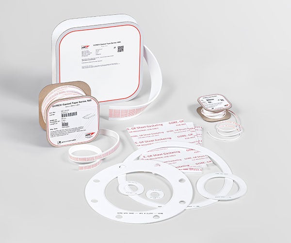
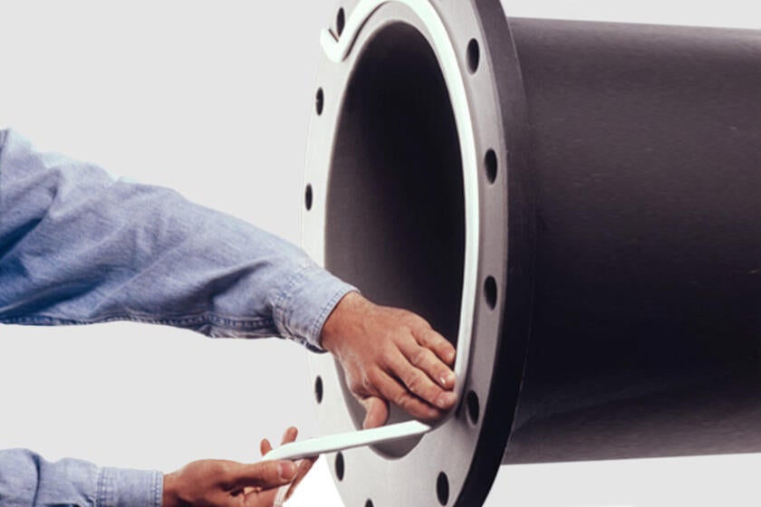
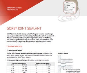
Supplied on a spool, this expanded ptfe joint sealant is fast and easy to install:
- Peel away the convenient backing strip.
- Apply the adhesive-backed sealant to the flange.
- Overlap the sealant ends to form a durable and reliable gasket.
With GORE Joint Sealant, even sealing vertical flanges is a one-person job.
|
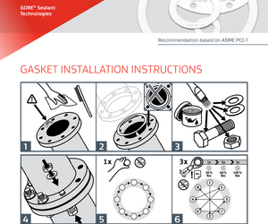
» See how easy it is to use GORE Joint Sealant: view our Installation Guide |
AN IMMEDIATE AND COST-SAVING SOLUTION
When time is money, Gore can help you save both
With GORE Joint Sealant, creating custom large gaskets on the spot is swift and simple, because your form in place gasket is immediately available. No need to wait for one to be fabricated off-site. No need for extra gaskets-and-seals procurement efforts to receive pallets, or requisition trucks or crane-lifts. No need for special handling or maintenance required, either.
Gasket creation and gasket installation are faster and easier with GORE Joint Sealant. Its tight, durable seal means maintenance is minimal, too. With fewer interruptions and less downtime, productivity is higher all around — and so are the related cost savings.
Technical Specifications
Test Data
Gasket Design Factors
Test Results
Please find below the EN 13555 test results:
GORE® Joint Sealant in 2 mm (0,08")
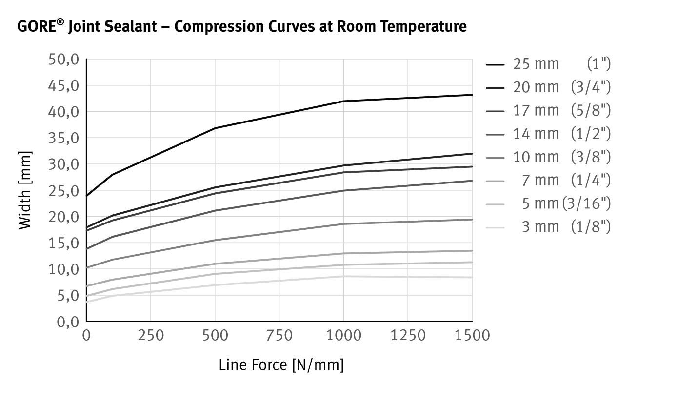
EN 13555 specifies a test flange that is DN 40 / PN 40 in size; therefore, GORE® Joint Sealant DF05 was tested using a stiffness of 500 kN/mm. Results for all other sizes were extrapolated from DF05 results using the following compression curve.
Test Method
EN 13555 provides the test method for generating the gasket parameters used in EN 1591-1 calculations. The informative Annex G now provides some guidance for generating gasket design parameters for form-in-place products.
Due to the material properties of monoaxially expanded PTFE, the increase in the gasket width of GORE® Joint Sealant depends on the pressure exerted on it. For the configuration and calculation of flange connections it is therefore easier to use line forces instead of gasket stress. The line force, Q*, is the ratio of the force per unit length.
Gasket Constant Definitions Modified for GORE® Joint Sealant
| PQR | A measure of creep relaxation at a predefined temperature. It is the ratio between the gasket stress after relaxation and the initial gasket stress. The ideal PQR value is 1. The closer the test value is to the ideal value, the lower the loss of gasket stress of the seal. |
|---|---|
| Q*min(L) | The minimum required line force at ambient temperature for a certain leakage class L when the seal is first installed. |
| Q*Smin(L) | The minimum required line force for a certain leakage class L in service. |
| Q*Smax | The maximum line force that may be applied on the gasket, without damage or intrusion into the bore, at the indicated temperatures. It depends on the temperature and the seal thickness. |
| E*G | This describes the recovery (elastic behavior) of a seal at load reduction. It is related to the modulus of elasticity. It depends on the applied line force, the seal thickness and the temperature. |
General Test Method Description
| PQR | Creep Relaxation is measured at different temperatures, initial gasket stress, seal thickness values and flange stiffness values. The seal initially is exposed to the predefined gasket stress, then the temperature is increased and maintained for four hours. The residual gasket stress is then measured. |
|---|---|
| Q*min Q*Smin |
A load is applied to and removed from the seal in predefined increments, with the leakage being measured constantly. The internal pressure is usually 40 bar (test gas: helium). |
| Q*Smax E*G |
The gasket stress is increased cyclically and then reduced to 1/3 of the previous gasket stress. The seal thickness is then measured. The test is repeated at various temperatures. The E*G value is calculated from the load reductions and thickness changes. For Q*Smax, a sudden drop in seal thickness indicates failure. If a sudden drop occurs, the value of the loading step before failure is taken. In case no failure occurs, the maximum possible gasket stress of the test equipment is taken. The identified value is then used as the initial stress in a PQR test to verify the final Q*Smax under constant loading. |
Q*min [N/mm]
| L1,0 | L0,1 | L0,01 | L0,001 | |
|---|---|---|---|---|
| 3 mm (1/8") | 37 | 65 | 97 | 129 |
| 5 mm (3/16") | 50 | 90 | 140 | 190 |
| 7 mm (1/4") | 68 | 119 | 183 | 244 |
| 10 mm (3/8") | 104 | 183 | 286 | 381 |
| 14 mm (1/2") | 146 | 261 | 411 | 554 |
| 17 mm (5/8") | 179 | 315 | 506 | 678 |
| 20 mm (3/4") | 190 | 344 | 546 | 734 |
| 25 mm (1") | 276 | 513 | 832 | 1128 |
Q*Smin [N/mm]
| Q*A [N/mm] | QA [MPa] | L1,0 | L0,1 | L0,01 | L0,001 | |
|---|---|---|---|---|---|---|
| 3 mm (1/8") | 100 | 33 | 37 | 37 | x | x |
| 200 | 67 | 37 | 37 | 37 | 88 | |
| 300 | 100 | 37 | 37 | 37 | 50 | |
| 400 | 133 | 37 | 46 | 55 | 65 | |
| 5 mm (3/16") | 100 | 20 | 50 | 50 | x | x |
| 200 | 40 | 50 | 50 | 50 | 135 | |
| 300 | 60 | 50 | 50 | 50 | 70 | |
| 400 | 80 | 50 | 60 | 75 | 90 | |
| 7 mm (1/4") | 100 | 14 | 68 | 68 | x | x |
| 200 | 29 | 68 | 68 | 68 | 162 | |
| 300 | 43 | 68 | 68 | 68 | 92 | |
| 400 | 57 | 68 | 85 | 101 | 119 | |
| 10 mm (3/8") | 100 | 10 | 104 | 104 | x | x |
| 200 | 20 | 104 | 104 | 104 | 250 | |
| 300 | 30 | 104 | 104 | 104 | 143 | |
| 400 | 40 | 104 | 129 | 156 | 183 | |
| 14 mm (1/2") | 100 | 7 | 146 | 146 | x | x |
| 200 | 14 | 146 | 146 | 146 | 353 | |
| 300 | 21 | 146 | 146 | 146 | 202 | |
| 400 | 29 | 146 | 183 | 221 | 261 | |
| 17 mm (5/8") | 100 | 6 | 179 | 179 | x | x |
| 200 | 12 | 179 | 179 | 179 | 435 | |
| 300 | 18 | 179 | 179 | 179 | 248 | |
| 400 | 24 | 179 | 224 | 272 | 317 | |
| 20 mm (3/4") | 100 | 5 | 190 | 190 | x | x |
| 200 | 10 | 190 | 190 | 190 | 464 | |
| 300 | 15 | 190 | 190 | 190 | 265 | |
| 400 | 20 | 190 | 240 | 291 | 344 | |
| 25 mm (1") | 100 | 4 | 276 | 276 | x | x |
| 200 | 8 | 276 | 276 | 276 | 683 | |
| 300 | 12 | 276 | 276 | 276 | 390 | |
| 400 | 16 | 276 | 351 | 430 | 513 |
X: The leakage rate is not achieved at the pre-compression line force Q*A as part of the measuring program.
Q*Smax
| PQR @ QSmax | QSmax | Q*Smax 1 | Temperature | |
| 5 mm (3/16") | 0.97 | 200 MPa (29,010 psi) |
1000 N/mm | Room |
| 0.89 | 200 MPa (29,010 psi) |
1000 N/mm | 80 °C (212 °F) |
|
| 0.92 | 200 MPa (29,010 psi) |
1000 N/mm | 150 °C (302 °F) |
1 Corresponds to inital gasket stress (initial width = 5 mm)
E*G
| EG | Gasket stress | Line force 1 | Temperature | |
| 5 mm (3/16") | 290 | 20 MPa (2,900 psi) | 100 N/mm | Room |
| 368 | 30 MPa (4,350 psi) | 150 N/mm | ||
| 438 | 40 MPa (5,800 psi) | 200 N/mm | ||
| 490 | 50 MPa (7,250 psi) | 250 N/mm | ||
| 527 | 60 MPa (8,700 psi) | 300 N/mm | ||
| 500 | 20 MPa (2,900 psi) | 100 N/mm | 80 °C (212 °F) |
|
| 581 | 30 MPa (4,350 psi) | 150 N/mm | ||
| 671 | 40 MPa (5,800 psi) | 200 N/mm | ||
| 817 | 50 MPa (7,250 psi) | 250 N/mm | ||
| 971 | 60 MPa (8,700 psi) | 300 N/mm | ||
| 260 | 20 MPa (2,900 psi) | 100 N/mm | 150 °C (302 °F) |
|
| 374 | 30 MPa (4,350 psi) | 150 N/mm | ||
| 380 | 40 MPa (5,800 psi) | 200 N/mm | ||
| 377 | 50 MPa (7,250 psi) | 250 N/mm | ||
| 369 | 60 MPa (8,700 psi) | 300 N/mm |
1 Corresponds to inital gasket stress (initial width = 5 mm)
Test Results
| m | 1.5 |
| y | 2500 |
Test Method
m & y are gasket constants used for flange design as specified in the ASME Boiler and Pressure Vessel Research Code Division 1 Section VIII Appendix 2. Leak Rates versus Y stresses and m factor for Gaskets is currently being proposed as a new test method in the ASTM F03 Working Group.
Gasket Constant Definitions
m, maintenance factor, is a factor that describes the amount of additional preload required to maintain the compressive load on a gasket after internal pressure is applied to a joint.
y, seating stress, is the minimum compressive stress (psi) required to achieve an initial seal.
Test Results
For GORE® Joint Sealant in 2 mm thickness and with an internal pressure of 10 bar
| k1 | 10 • bD |
| k0KD | 18 MPa • bD |
| k0KDϑ | 200 MPa • bD temperature ϑ = 150 °C (302 °F) |
Test Method
There are no specific test standards for AD 2000 B 7 Gasket Parameters. However, an estimation is provided below. The 2015 edition of "AD 2000-Merkblatt B 7" refers to EN 13555 as a test standard(1) and uses table 9 from VDI 2200(2) for the conversion method. Please note that VDI 2200 states that such a conversion is invalid due to the different measurement methods. "Only the method according to DIN EN 1591-1 and AD 2000 in conjunction with DIN EN 1591-1 and FE analysis can be used for providing stability, leak tightness and TA Luft proof." (3)
Gore supports the use of the AD 2000-Merkblatt B 7 and provides the necessary gasket parameters below.
There are the following relations(1):
k0KD ≙ Qmin · bD
k1 ≙ (QSmin / p) · bD since m ≙ QSmin / p (4)
k0KDϑ ≙ Qsmax · bD
| Qmin | minimum required gasket stress at ambient temperature when the seal is first installed (based on EN13555) |
|---|---|
| QSmin | minimum required gasket stress in service (based on EN13555) |
| QSmax | maximum gasket stress that may be applied on the gasket at an indicated temperature ϑ (based on EN 13555) |
| bD | width of the gasket |
| p | internal pressure of the media |
| k1 | AD 2000 B7 gasket parameter for service condition |
| k0KD | AD 2000 B7 gasket parameter for gasket deformation |
| k0KDϑ | AD 2000 B7 gasket parameter for gasket deformation in service at temperature ϑ |
If necessary for a specific application, Gore recommends to do individual conversions based on data from EN 13555.
The use of the general values given in table 1 of AD 2000-Merkblatt B 7(5) is not broadly recommended. However they may be applicable depending on the given situation.
Please also note that the quoted standards of DIN 2690 to DIN 2692 were superseded by EN 1514-1 in 1997.
(1) Arbeitsgemeinschaft Druckbehälter: AD 2000-Merkblatt B 7, Berechnung von Druckbehältern, Schrauben, Seite 4, 7.1.2.4, April 2015
(2) Verein Deutscher Ingenieure e. V.: VDI 2200, Tight flange connections - Selection, calculation, design and assembly of bolted flange connections, page 36, table 9, June 2007
(3) Verein Deutscher Ingenieure e. V.: VDI 2290, Emission Control - Sealing constants for flange connections, page 8, June 2012
(4) Please note that factor m = QSmin / p was defined by DIN V 2505 which was superseded by EN 1591-1 where m is no longer used
(5) Arbeitsgemeinschaft Druckbehälter: AD 2000-Merkblatt B 7, Berechnung von Druckbehältern, Schrauben, Seite 6, Tabelle 1, April 2015
CERTIFICATES & APPLICATION INFORMATION
Resources

Data Sheet: GORE® Joint Sealant
Data Sheets,
Installation Guide: GORE® Joint Sealant
Installation Guides,
Installation Guide: Bolted Flange Assembly Instructions
Installation Guides,
FOR INDUSTRIAL USE ONLY
Not for use in food, drug, cosmetic or medical device manufacturing, processing, or packaging operations.