GORE® PHASEFLEX® Microwave/RF Test Assemblies
For test applications that require precise, repeatable measurements, microwave/RF test assemblies from Gore provide excellent phase and amplitude stability with flexure. Our rugged, lightweight assemblies deliver reliable performance with longer service life and reduced equipment downtime resulting in lower costs for testing in laboratory, production and field test environments.
Contact Us
+1 800 356 4622
Germany
+49 9144 6010
+49 9144 6816 (fax)
UK
+44 1382 56 1511
+44 1382 56 1007 (fax)
Italy
+39 045 6209 209
+39 045 6209 165 (fax)
France
+33 1 5695 6565
+33 1 5695 6401 (fax)
Spain
+34 93 480 6900
+34 93 373 7850 (fax)
Sweden
+46 31 7067800
+46 31 864226 (fax)
China (Beijing)
+86 10 5707 4999
+86 10 5707 4900 (fax)
China (Shanghai)
+86 21 5172 8299
+86 21 6247 9199 (fax)
China (Shenzhen)
+86 755 8359 8262
+86 755 8359 1654 (fax)
South Korea
+82 2 393 3411
+82 2 393 1285 (fax)
Japan
+81 3 6746 2582
+81 3 6746 2571 (fax)
Resource Library
Designed for test applications that depend on accurate, repeatable measurements, W. L. Gore & Associates offers GORE® PHASEFLEX® Microwave/RF Test Assemblies, which provide excellent mechanical durability and electrical performance. Our RF cable assemblies not only feature a rugged construction that prolongs service life, but they also offer high phase and amplitude stability for high-density and modular test applications at an affordable price. To optimize the performance of the assembly even further, they can also be paired with Gore’s available connectors.
All Resources For GORE® PHASEFLEX® Microwave/RF Test Assemblies
- Videos (8)
- Interactives (1)
- Industry Articles (6)
- Product Selection Guides (1)
- White Papers (7)
- Technical Information (8)
- Part Number Information (2)
- Authorized Distributors (1)
- Data Sheets (1)
Overview
In today’s competitive electronics industries, reliability is essential for applications that use microwave/RF cable assemblies to ensure consistent, repeatable measurements and to maintain electrical performance over time. So, cable assemblies must be durable enough to withstand continuous movement, flexing, and exposure to environmental conditions while maintaining reliable electrical performance. But, a recent study showed that globally more than 75% of microwave/RF cable assemblies are replaced frequently due to damage during installation or operation.
Durable, Reliable Performance Now and Over Time
GORE® PHASEFLEX® Microwave/RF Test Assemblies has been recognized among the 2020 Military & Aerospace Electronics Innovators Awards. Learn more
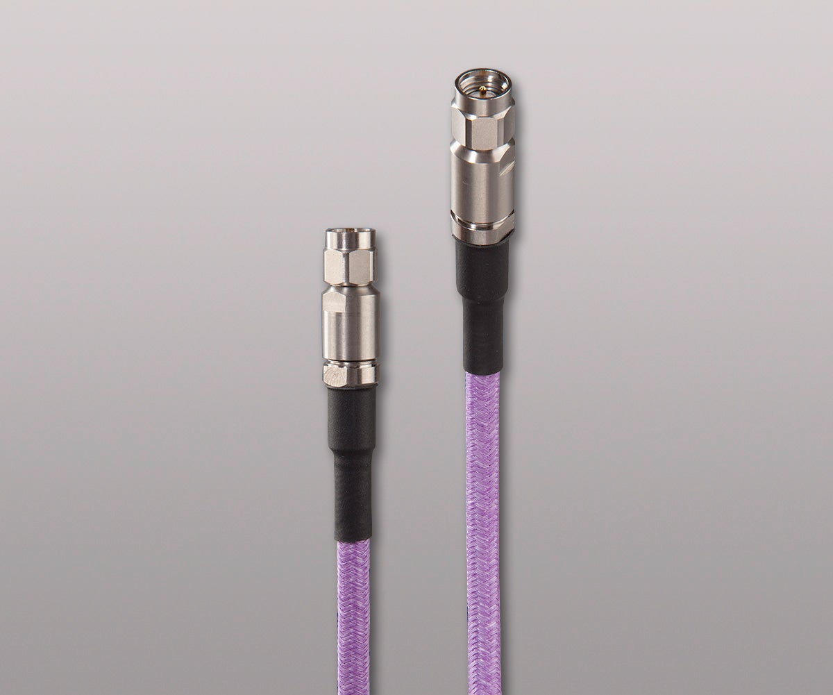
GORE PHASEFLEX Microwave/RF Test Assemblies are the only internally ruggedized, flexible RF test assembly that provides consistent electrical performance with long service life in demanding environments. Our assemblies have a durable construction that resists not only crushing, but also kinking and twisting to prevent damage that could be caused by exceeding a cable’s minimum bend radius. Our assemblies also maintain precise, repeatable measurements, while withstanding frequent connecting and disconnecting, and they perform reliably even after extensive flexing with some cable constructions exceeding 100,000 flex cycles.
So, can you justify replacing your microwave/RF assemblies several times a year? Or, would you rather use one assembly for the life of your test equipment? GORE PHASEFLEX Microwave/RF Test Assemblies are more reliable and last longer than typical cable assemblies used in the industry — years rather than months.
GORE PHASEFLEX Microwave/RF Test Assemblies provide unmatched precision, repeatability and durability over time.
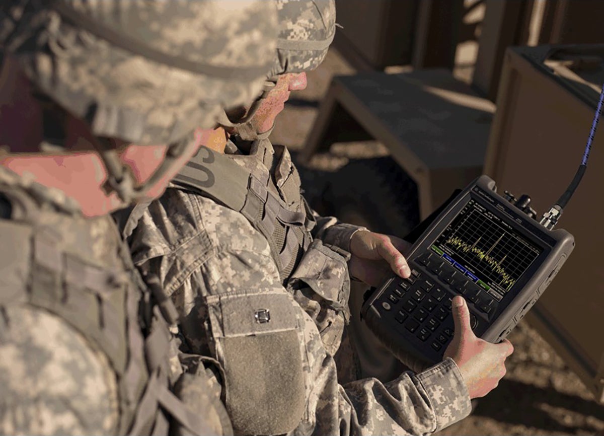
Applications
GORE PHASEFLEX Microwave/RF Test Assemblies are engineered to perform reliably in a variety of test and measurement applications, including:
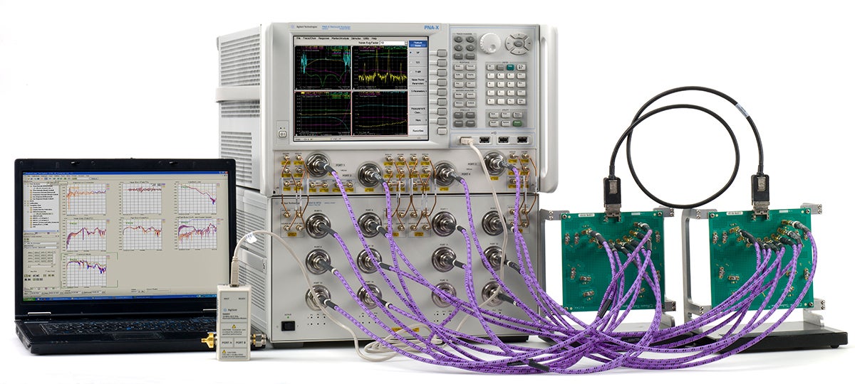
Courtesy, Keysight Technologies, Inc.
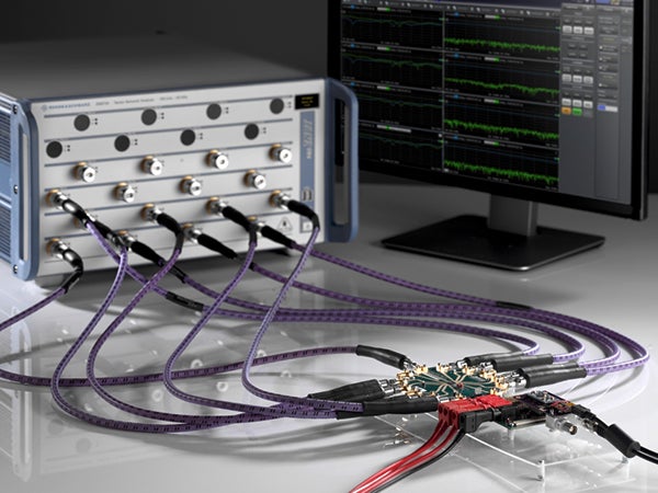
Application on R&S®ZNBT Vector Network Analyzer.
Courtesy, Rohde & Schwarz GmbH & Co.
- anechoic chambers
- antenna ranges
- automated test equipment
- bench-top testing
- electromagnetic compliance testing
- high throughput RF production testing
- nearfield scanners
- portable analyzers
- scalar network analyzers
- test rack systems
- vector network analyzers (VNAs)
- wireless telecommunication module testing
- thermal vacuum chambers
- high speed digital test
- 5G test and interconnection
If you have any questions or to discuss your specific application needs, please contact a Gore representative.
Features and Benefits
We have engineered features for GORE PHASEFLEX Microwave/RF Test Assemblies that make them more durable in demanding environments. Features include:
- torque, crush and kink resistance
- abrasion resistance
- dust and moisture resistance
- chemical resistance
- wide temperature range
- high connector pull strength
Our test assemblies provide manufacturers with many benefits that improve electrical and mechanical performance such as:
- consistent, repeatable measurements with stable electrical performance up to 110 GHz
- longer service life with durable construction that resists crushing, twisting and kinking
- enhanced phase and amplitude stability with flexure and temperature
- increased throughput and reduced downtime with durable and reliable performance
- a variety of connector options specifically engineered to optimize assembly performance
For more information about the features and benefits of our test assemblies, please contact a Gore representative.
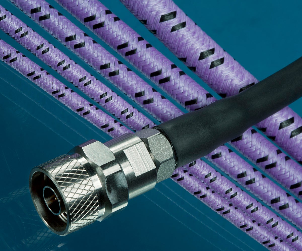
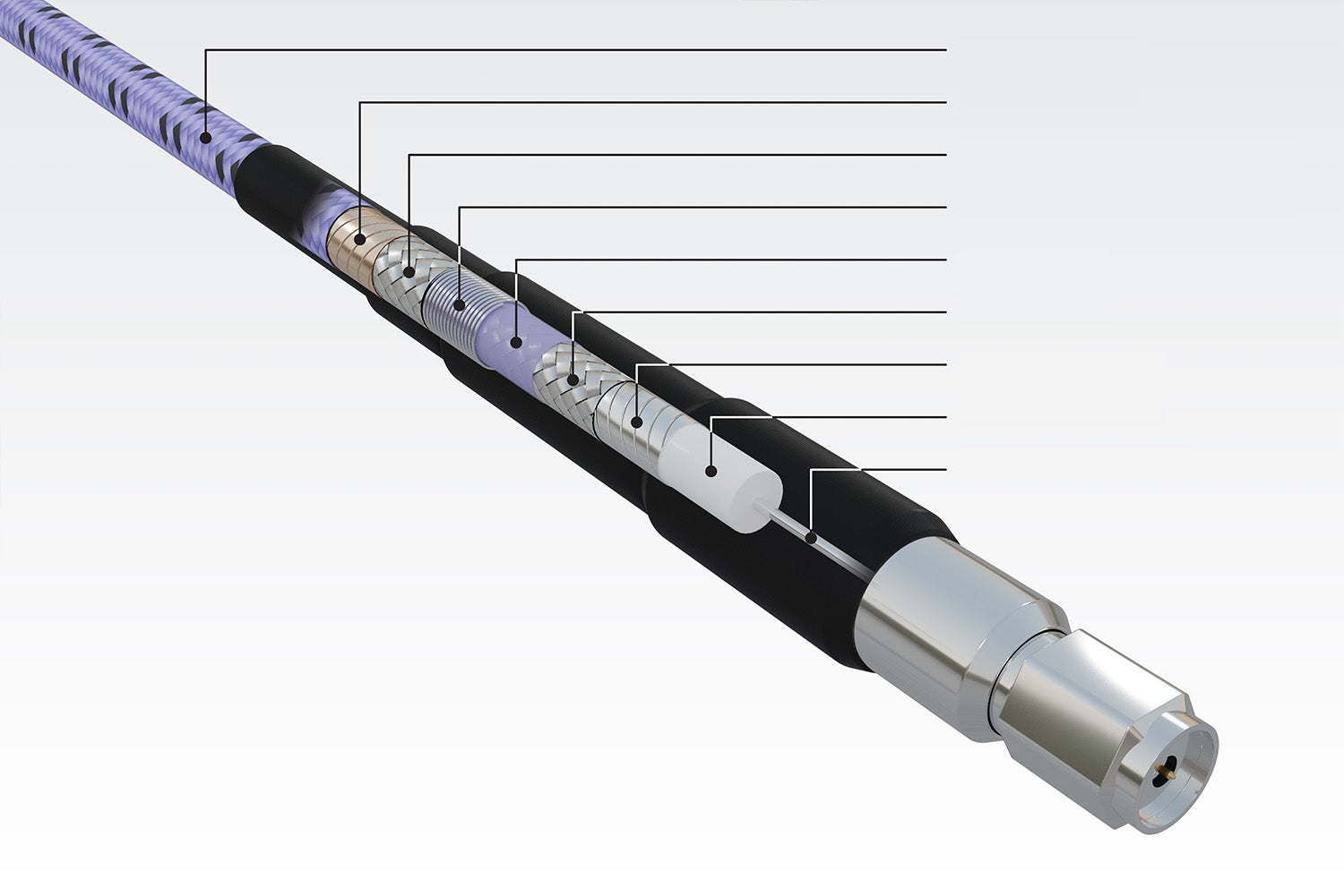
Construction of GORE® PHASEFLEX® Microwave/RF Test Assemblies
Videos
Go to our YouTube Channel to watch these and other videos of Gore engineers demonstrating the benefits of GORE® Microwave/RF Assemblies.
Resources

Gore Product Selection Guide for 5G Test Systems
Product Selection Guides
View all resources for PHASEFLEX Microwave/RF Test Assemblies
Recent News
Visit Booth 136 to see Gore’s custom-fit static and high flex cables and assemblies designed for lithography and built for you. Our solutions meet stringent industry standards around cleanliness, durability, outgassing performance and flexibility.
Clean Gore cables & assemblies: Made for lithography. Made for you. Gore’s custom-configured static and high-flex cables & cable assemblies are designed, engineered and manufactured to meet the lithography industry’s toughest standards for durability, outgassing performance, cleanliness and flexibility. We look forward to seeing you at Precisiebeurs 2022.
Gore is exhibiting virtually at this year’s International Microwave Symposium (IMS), and you’re invited to visit our virtual booth. We’ll describe how our proven portfolio of durable microwave/RF test assemblies delivers stable and consistent performance for reliable 5G test results.
Press Release
GORE® PHASEFLEX® Microwave/RF Test Assemblies Honored, Set Gold Standard with Industry Innovators Award
Posted September 16, 2020
W. L. Gore & Associates announced that its GORE® PHASEFLEX® Microwave/RF Test Assemblies were recognized among the 2020 Military & Aerospace Electronics Innovators Awards. An esteemed and experienced panel of judges from the aerospace and defense community recognized Gore as a Gold honoree. These assemblies are being recognized for their durability and reliability for precision testing of electronic warfare (EW) / radar suites; electronic surveillance/counter measures; radar warning systems; missile approach warning systems; and navigation/communication systems.
FOR INDUSTRIAL USE ONLY
Not for use in food, drug, cosmetic or medical device manufacturing, processing, or packaging operations.
Follow GORE® PHASEFLEX® Microwave/RF Test Assemblies